A temperature-controlled quenching device for automotive synchronizer gears

A technology of quenching device and synchronizer, which is applied in the direction of quenching device, heat treatment process control, furnace, etc., can solve the problems of affecting cooling work efficiency, uneven thermal expansion and cooling, uneven cooling of workpieces, etc., to prevent uneven cooling, realize The effect of homogenizing the temperature and improving the cooling efficiency

Active Publication Date: 2019-11-29
安徽扬子职业技术学院
View PDF7 Cites 0 Cited by
  • Summary
  • Abstract
  • Description
  • Claims
  • Application Information

AI Technical Summary

Problems solved by technology

[0006] (1) The general quenching device is to place the workpiece on the transmission chain in the tank. Due to the influence of the cooling medium on the buoyancy of the gear workpiece, it is possible that the gear workpiece will accumulate on the transmission chain, which will affect the cooling efficiency.
[0007] (2) It is easy to cause uneven cooling of the workpiece and cause deformation. There is a certain difference in the cooling rate between the surface and the core. If the difference is large enough, it may cause the part greater than the critical cooling rate to transform into martensite, but less than the critical cooling rate. The center of the core cannot be transformed into martensite, or the cooling rate is too fast. During the cooling process of the workpiece, the internal stress may be caused by the uneven thermal expansion and contraction inside the workpiece, which may deform or crack the workpiece.

Method used


Image

  • A temperature-controlled quenching device for automotive synchronizer gears
  • A temperature-controlled quenching device for automotive synchronizer gears
  • A temperature-controlled quenching device for automotive synchronizer gears

Examples


Embodiment Construction

[0040]The following will clearly and completely describe the technical solutions in the embodiments of the present invention with reference to the accompanying drawings in the embodiments of the present invention. Obviously, the described embodiments are only some, not all, embodiments of the present invention. Based on the embodiments of the present invention, all other embodiments obtained by persons of ordinary skill in the art without making creative efforts belong to the protection scope of the present invention.

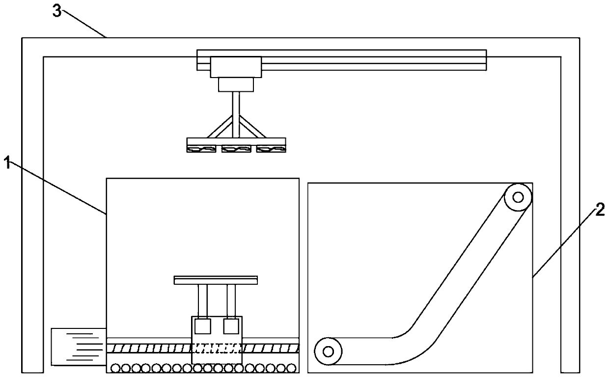
[0041] Such as figure 1 As shown, the present invention provides a temperature-controlled quenching device for synchronizer gears for automobiles, including a primary brine quenching mechanism 1, a secondary cold water quenching mechanism 2, and a primary brine quenching mechanism 1 and a secondary cold water quenching mechanism 2 The three-stage air-cooling mechanism 3 above, the first-stage brine quenching 1 uses brine quenching medium to perform the first ro...


PUM


Abstract

The invention discloses a temperature control quenching device for a synchronizer gear for an automobile. The temperature control quenching device comprises a first-level saline water quenching mechanism, a second-level saline water quenching mechanism and a third-level saline water quenching mechanism, wherein the third-level saline water quenching mechanism is arranged above the first-level saline water quenching mechanism and the second-level saline water quenching mechanism. The first-level saline water quenching mechanism comprises a quenching tank body and an ascending-and-descending cooling table. The ascending-and-descending cooling table comprises a movable sliding block and an ascending-and-descending extending-and-contracting air cylinder. An extending-and-contracting rod of theascending-and-descending extending-and-contracting air cylinder is connected with a carrying base plate. A first driving motor is connected to the outer side of the quenching tank body. The first driving motor is connected with a rotary lead screw. The movable sliding block is internally provided with a rolling ball groove, wherein the rolling ball groove moves on the rotary lead screw. Sliding track plates are mounted at the bottom of the quenching tank body. Multiple rolling ball connecting rods are arranged between the two sliding track plates, wherein the rolling ball connecting rods aredistributed in an equally-spaced manner. The temperature control quenching device is used by combing three cooling modes, and rapid cooling treatment can be conducted on a gear workpiece; meanwhile, temperature control treatment is conducted on a cooling medium, and cooling efficiency is improved; and quality, achieved in the quenching process, of the gear is guaranteed, and strength and stiffnessof the gear are improved.

Description

technical field [0001] The invention relates to the technical field of automobile gear manufacturing, in particular to a temperature-controlled quenching device for automobile synchronizer gears. Background technique [0002] Anyone who knows a little about cars knows that many mechanisms in cars use gear transmission. For example, the gearbox of a car is a complex gear transmission mechanism. Others include drive axles, differentials, steering gears, etc., and even some electrical components, such as window lifters, wipers, and electronic handbrakes. Gear transmission is also used in the device. [0003] The shifting of the old-fashioned transmission adopts the "two-leg clutch" method, and the upshift stays in the neutral position for a while (but the clutch needs to be lifted up, the purpose is to synchronize the clutch plate with the flywheel, and the speed must be consistent before the gear can be smoothly shifted , if the gear shifting is slow and the speed drops to i...

Claims


Application Information

Patent Timeline
Patent Type & Authority Patents(China)
IPC IPC(8): C21D1/64C21D9/32C21D11/00
CPCC21D1/64C21D9/0062C21D9/32C21D11/005
Inventor 张阳姚晓峰李龙
Owner 安徽扬子职业技术学院
Why Eureka
Try Eureka