Oscillating blade type wave energy electricity generation device
A power generation device and wave energy technology, which is applied to ocean power generation, hydropower generation, reaction engines, etc., can solve problems such as scattered structures, complex systems, and difficult installation
- Summary
- Abstract
- Description
- Claims
- Application Information
AI Technical Summary
Problems solved by technology
Method used
Image

Examples
Embodiment 1
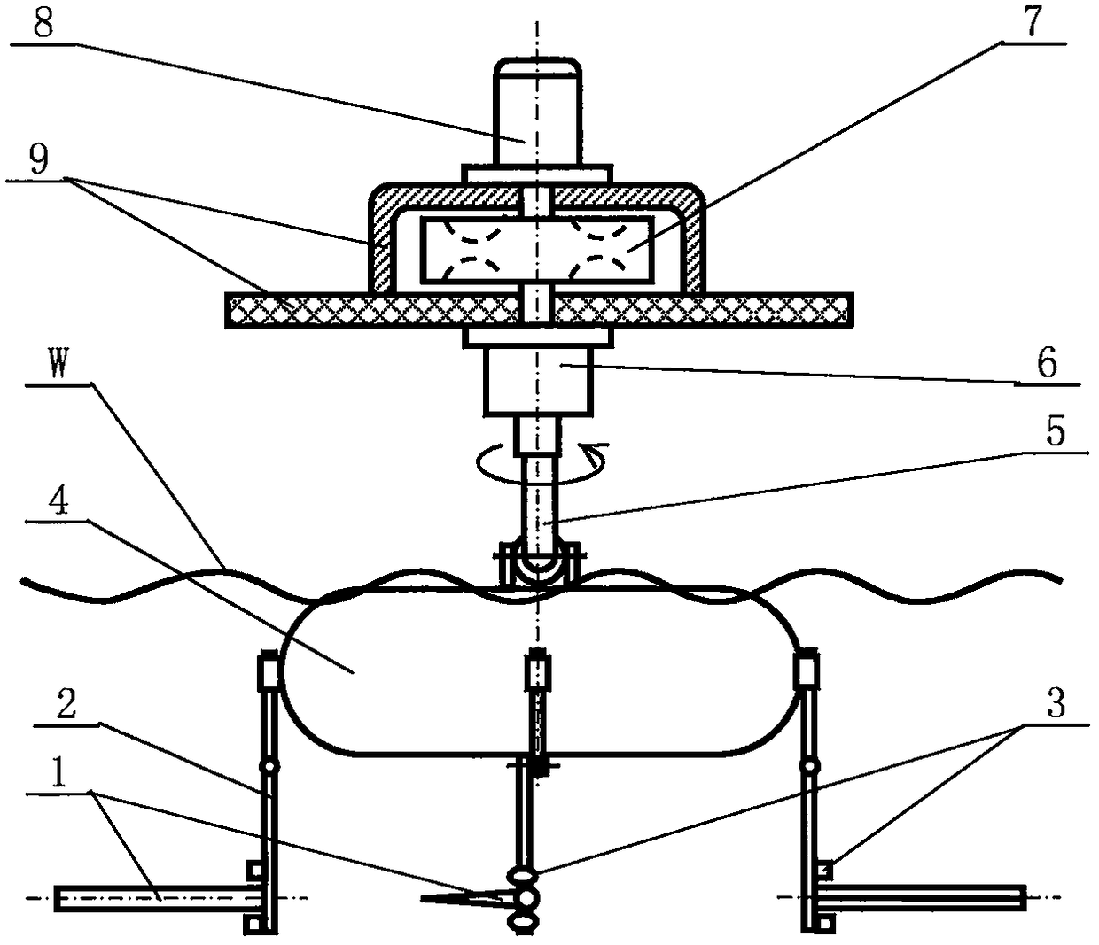
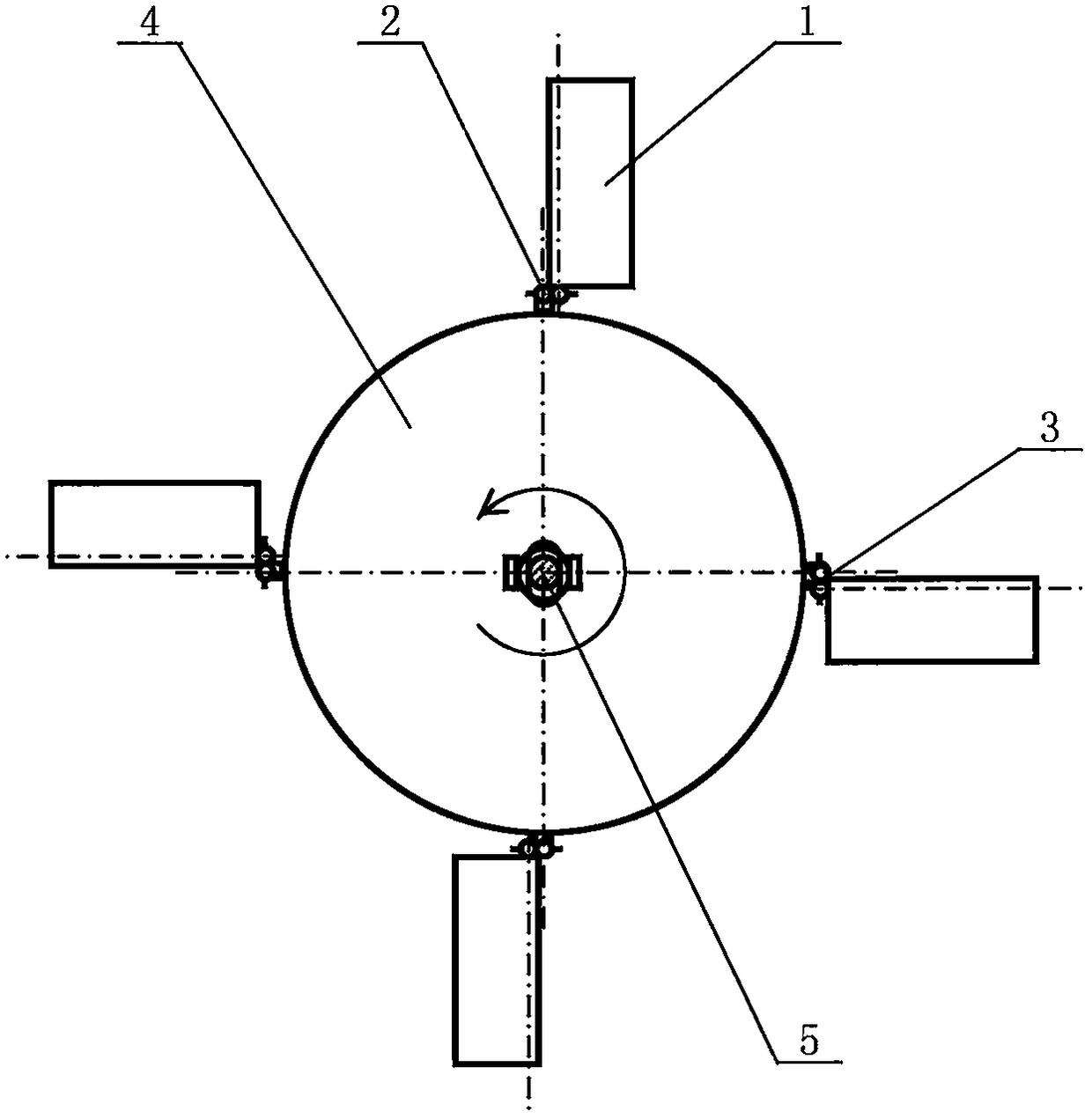
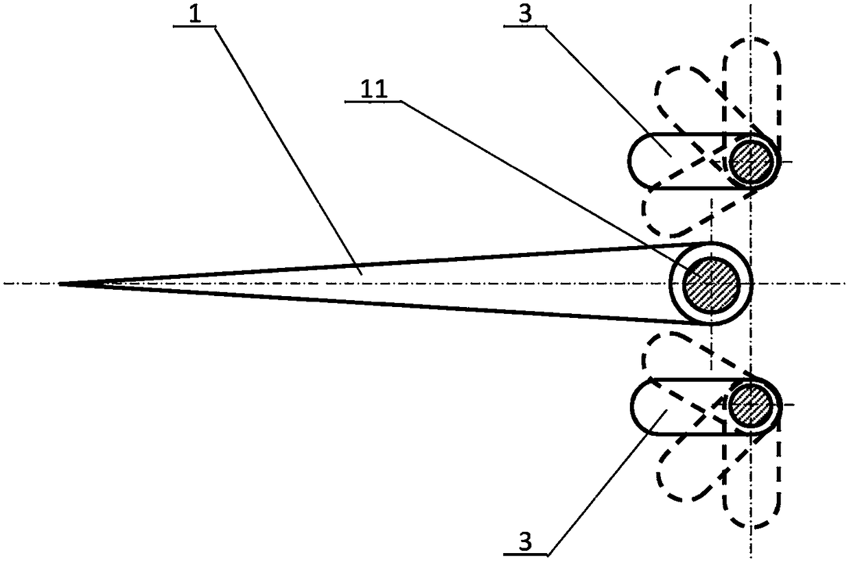
[0022] Such as figure 1 and figure 2 As shown, a swing-blade wave energy generating device has a structural form of a one-to-one configuration of a circular rotating floating body, a swing leaf and a swing leaf frame. It includes a swing leaf 1, a swing leaf frame 2, a swing limiter 3, a floating body 4, a transmission shaft 5, a gearbox 6, a flywheel 7, a generator 8 and a fixed stand 9. Described pendulum blade 1 is a kind of streamlined blade, and there is a shaft 11 near the leading edge (referring to image 3 ), the swing blade 1 and the shaft 11 are not fixed, but can rotate relative to each other. The swing leaf frame 2 is divided into two sections from the middle hinge, the upper half section is fixed on the floating body 4, and the bottom half section is connected to the swing leaf 1 at the end. There are 4 (or more) sets of swing leaves 1 and their swing leaf holders 2, which are arranged and fixed along the outer circumference of the floating body 4, and the sha...
Embodiment 2
[0027] Such as Figure 4 and Figure 5 As shown in Fig. 1 , a swing-blade type wave energy generating device has a structure of a non-rotating floating body, and all swing leaves share a swing-leaf frame. It includes a swing leaf 1, a swing leaf frame 2, a swing limiter 3, a floating body 4, a transmission shaft 5, a gearbox 6, a flywheel 7, a generator 8 and a fixed stand 9. Described pendulum blade 1 is a kind of streamlined blade, and there is a shaft 11 near the leading edge (referring to Figure 6 ), the swing leaf 1 is fixed to the shaft 11, and the root of the shaft 11 has a protruding handle. The swing leaf frame 2 is cylindrical and shared by all swing leaves. The shaft 11 of the swing leaf 1 is arranged radially perpendicular to the transmission shaft 5 . The swing limiter 3, under the action of its drive mechanism, adjusts the stopper spacing (see Figure 6 The swing limiter 3) is used to change the swing angle of the swing blade 1 to adjust the output power. T...
PUM
 Abstract
Description
Claims
Application Information
 - R&D Engineer
- R&D Manager
- IP Professional
- Industry Leading Data Capabilities
- Powerful AI technology
- Patent DNA Extraction
Browse by: Latest US Patents, China's latest patents, Technical Efficacy Thesaurus, Application Domain, Technology Topic.
© 2024 PatSnap. All rights reserved.Legal|Privacy policy|Modern Slavery Act Transparency Statement|Sitemap