High-power gyrotron collecting stage

A gyrotron and high-power technology, which is applied to collectors of time-of-flight electron tubes, discharge tubes, and time-of-flight electron tubes. required effect

Inactive Publication Date: 2018-08-14
UNIV OF ELECTRONICS SCI & TECH OF CHINA
View PDF2 Cites 2 Cited by
  • Summary
  • Abstract
  • Description
  • Claims
  • Application Information

AI Technical Summary

Problems solved by technology

University of Electronic Science and Technology of China Jiang Wei, Yan Ran and others proposed a curved collector stage in the Design of Curved Collector for Q Band Gyro-TWT of the "IEEE Vacuum Electronics Conference" conference in 2015, which is used to collect power density of 0.38kw / cm 2 , the collection stage is used for the gyrotraveling wave tube in the Q band. The working temperature of the collection stage is controlled at 142°C, and the effect is good. However, when the structure collects higher power densities, it may spark due to excessive temperature.

Method used


Image

  • High-power gyrotron collecting stage
  • High-power gyrotron collecting stage
  • High-power gyrotron collecting stage

Examples


Embodiment 1

[0020] A high-power gyrotron collection stage, which includes a cylindrical inner wall and a plurality of cooling fins arranged outside the inner wall, is characterized in that each cooling fin is in a spiral structure around the outer side of the inner wall, and the gap between adjacent cooling fins The gap is a spiral coolant channel. The bottom of the spiral cooling liquid channel (that is, the outer side of the cylindrical inner wall) is a corrugated structure. Further, the collection stage includes 48 cooling fins, the cooling liquid channel is 1 mm wide, the helix angle of each cooling fin is 360 degrees, the cylindrical inner wall radius is 15 mm, the collection stage length is 50 mm, and the wall thickness is 1.5 mm. The coolant channels are 7.5mm deep.

Embodiment 2

[0022] A high-power gyrotron collection stage, which includes a cylindrical inner wall and a plurality of cooling fins arranged outside the inner wall, is characterized in that each cooling fin is in a spiral structure around the outer side of the inner wall, and the gap between adjacent cooling fins The gap is a spiral coolant channel. The bottom of the spiral cooling liquid channel (that is, the outer side of the cylindrical inner wall) is a corrugated structure. Further, the collection stage includes 36 cooling fins, the cooling liquid channel is 1.5mm wide, the helix angle of each cooling fin is 360 degrees, the cylindrical inner wall radius is 15mm, the collection stage length is 50mm, and the wall thickness is 1.5mm. The coolant channels are 7.5mm deep.

Embodiment 3

[0024] A high-power gyrotron collection stage, which includes a cylindrical inner wall and a plurality of cooling fins arranged outside the inner wall, is characterized in that each cooling fin is in a spiral structure around the outer side of the inner wall, and the gap between adjacent cooling fins The gap is a spiral coolant channel. The bottom of the spiral cooling liquid channel (that is, the outer side of the cylindrical inner wall) is a corrugated structure. Further, the collection stage includes 24 cooling fins, the cooling liquid channel is 2mm wide, the helix angle of each cooling fin is 360 degrees, the cylindrical inner wall radius is 15mm, the collection stage length is 50mm, and the wall thickness is 1.5mm. The coolant channels are 7.5mm deep.

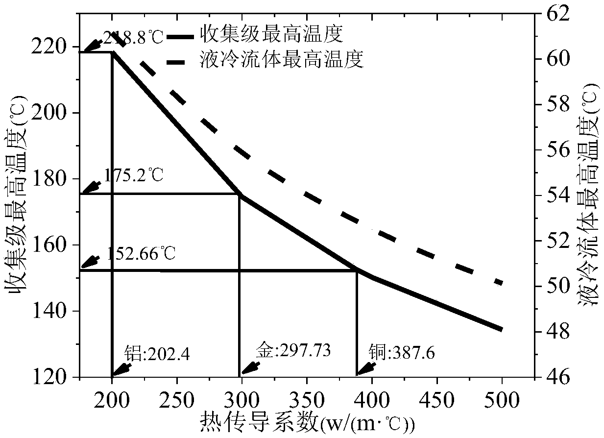
[0025] refer to figure 1 As shown in Fig. 1, increasing the thermal conductivity of the collection-level material can quickly transfer the dissipated power per unit area to the low-temperature region. When the dissipati...


PUM


Abstract

The invention discloses a high-power gyrotron collecting stage, which belongs to the field of high-power technologies of microwaves and millimeter waves, relates to a high-power gyroscope, and is a novel collecting stage structure for a high-power gyrotron. The collecting stage comprises a cylindrical inner wall and a plurality of cooling fins arranged outside the inner wall, wherein each coolingfin is of a spiral structure and surrounds the outer side of the inner wall, and a gap between the adjacent cooling fins is a spiral coolant passage; and the bottom of the spiral coolant passage is acorrugated structure. Through the design of the collecting stage with a special structure, the liquid cooling efficiency can be greatly improved, the collecting stage and the liquid cooling temperature can be lowered, and thus the power density per unit area of the collecting stage can be increased from 0.38kw/cm2 to 1.65kw/cm2, the collecting requirements of the gyroscopes with higher power can be met, and a smaller size can be realized.

Description

technical field [0001] The invention belongs to the technical field of microwave and millimeter wave high power, relates to a high-power gyrotron device, and is a novel collecting stage structure for a high-power gyrotron. Background technique [0002] As the first choice for high-power sources in the millimeter wave band, the gyrotron device has a power capacity of hundreds of kW, and the power capacity of the oscillation device has even reached the M watt level. It is used in high-resolution imaging radar, electronic countermeasures, and secure satellite communications. It has a very broad application prospect. Among them, the collection stage is a component that effectively collects the remaining electrons after the injection-wave interaction, and its design is the key link to ensure high power output. However, due to the limitation of the power capacity per unit area of ​​the collection stage, when the average power of the gyrotron device is higher, the remaining electr...

Claims


Application Information

Patent Timeline
Patent Type & Authority Applications(China)
IPC IPC(8): H01J23/027H01J23/00
CPCH01J23/027H01J23/00
Inventor 王迪鄢然罗勇
Owner UNIV OF ELECTRONICS SCI & TECH OF CHINA
Why Eureka
Try Eureka