Supercharge Your Innovation With Domain-Expert AI Agents!

A two-degree-of-freedom micro-gripper

A technology of micro-clamping and degree of freedom, which is applied in the direction of collets, micro-manipulators, manufacturing tools, etc., can solve the problems of limiting the application range of micro-grippers and failing to meet the application fields of micro-grippers, and achieve measurement and real-time Feedback, improving static and dynamic characteristics, reducing the overall mass and the effect of motion inertia

Active Publication Date: 2020-11-20
TIANJIN UNIV
View PDF5 Cites 0 Cited by
  • Summary
  • Abstract
  • Description
  • Claims
  • Application Information

AI Technical Summary

Problems solved by technology

[0003] Most of the traditional micro grippers have only one degree of freedom, which cannot meet the application fields that have higher requirements for the degree of freedom of micro grippers, which seriously limits the application range of micro grippers

Method used


Image

  • A two-degree-of-freedom micro-gripper
  • A two-degree-of-freedom micro-gripper
  • A two-degree-of-freedom micro-gripper

Examples


Embodiment Construction

[0019] The present invention will be further described below in conjunction with the drawings.

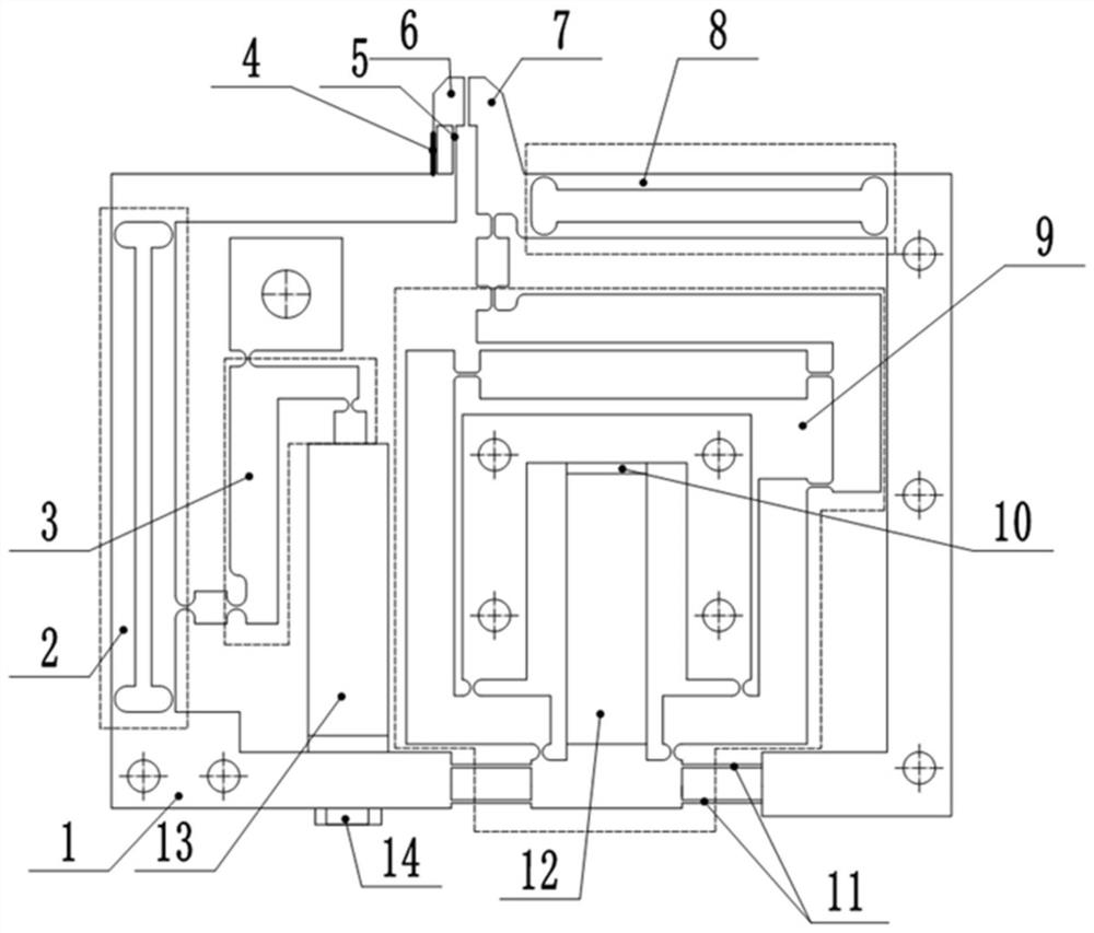
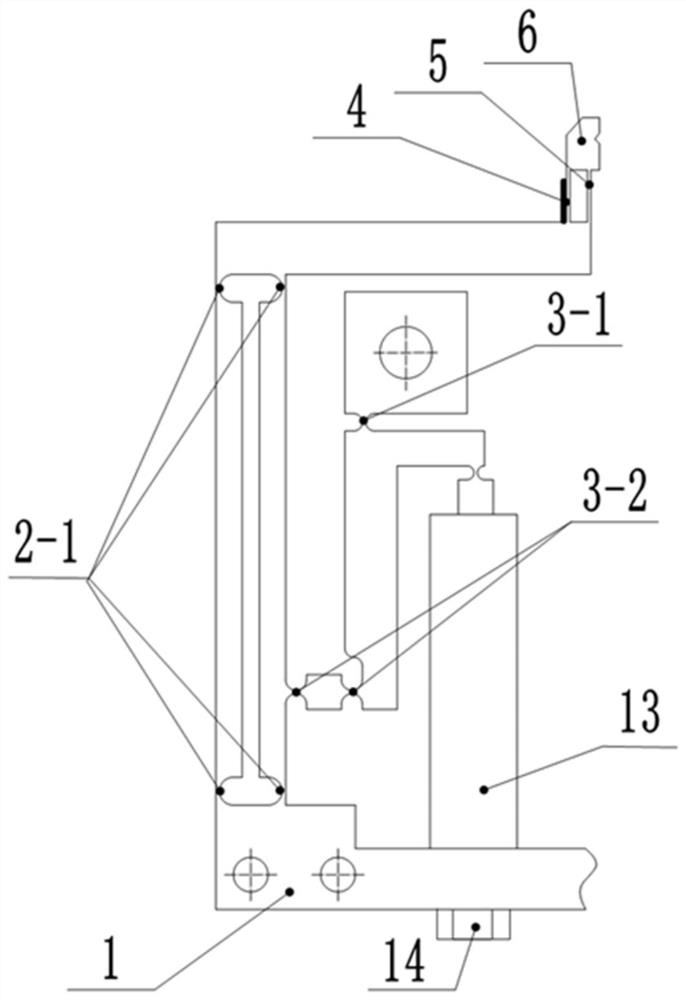
[0020] See Figure 1 ~ Figure 5 , A two-degree-of-freedom micro-gripper, which is formed by wire cutting of sheet metal and includes a lever displacement amplifying mechanism 3, a differential displacement amplifying mechanism 9 and a base 1, a lever displacement amplifying mechanism 3 and a differential displacement The magnifying mechanism 9 is respectively located on the left and right sides of the holder.

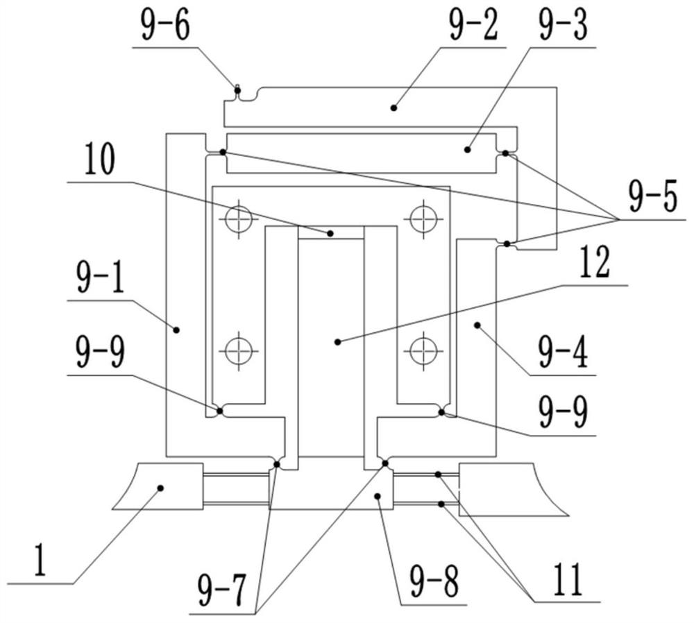
[0021] The differential displacement amplifying mechanism 9 is provided with input rods 9-8, L-shaped rods Ⅰ 9-1, L-shaped rods Ⅱ 9-2, L-shaped rods Ⅲ 9-4 which are connected to the base body 1, and parallel to the X axis Connecting rod 9-3; both ends of the input rod 9-8 are each formed with a flexible double parallel plate mechanism I11 connected to the base 1, and a piezoelectric ceramic driver I12 is provided between the input rod 9-8 and the base 1. , Piezoelectric ceramic...


PUM


Abstract

The invention discloses a two-degree-of-freedom microgripper. The microgripper is of an asymmetrical structure integrally formed by linearly cutting a panel, and comprises a differential displacementmagnifying mechanism, a lever displacement magnifying mechanism and a base body, wherein the differential displacement magnifying mechanism is arranged on the right side of a center line of the gripper; the lever displacement magnifying mechanism is arranged on the left side of the center line of the gripper; the differential displacement magnifying mechanism is provided with an L-shaped rod pieceI, an L-shaped rod piece II, an L-shaped rod piece III, an input rod piece and a horizontal rod piece; the lever displacement magnifying mechanism and the base body are connected by adopting a flexible hinge III; an input end and an output end are arranged at two ends of the lever displacement magnifying mechanism; and the input end of the lever displacement magnifying mechanism is driven througha piezoelectric ceramic actuator II. The two-degree-of-freedom microgripper provided by the invention is small in volume and compact in structure, has two degrees of freedom, low manufacturing cost,and larger displacement magnifying times, can realize clamping force measurement and feedback, and can be applicable to different application fields.

Description

Technical field [0001] The invention belongs to the field of micro-device assembly, and particularly relates to a two-degree-of-freedom micro holder. Background technique [0002] In recent years, with the vigorous development of the microelectronics industry, the development of the microelectronics industry has become an important indicator of a country's comprehensive strength, and an important guarantee for promoting the sustainable development of the national economy and the security of the country's strategic basic industries. With the continuous development of the microelectronics industry, its related industry devices continue to develop in the direction of miniaturization, high performance and high integration. The quality requirements for assembly and operation are becoming more and more stringent. Therefore, the quality and efficiency of micro device packaging are proposed higher requirement. [0003] Most of the traditional micro-grippers have only one degree of freedom...

Claims


Application Information

Patent Timeline
Patent Type & Authority Patents(China)
IPC IPC(8): B25J7/00B25J15/00B25J15/02
CPCB25J7/00B25J15/00B25J15/0253
Inventor 时贝超王福军赵兴玉梁存满霍至琛田延岭
Owner TIANJIN UNIV
Features
  • R&D
  • Intellectual Property
  • Life Sciences
  • Materials
  • Tech Scout
  • Unparalleled Data Quality
  • Higher Quality Content
  • 60% Fewer Hallucinations
Learn More