
Flexible connecting structure for old and new bridges and construction method of flexible connecting structure

A flexible connection and bridge technology, which is applied in bridges, bridge parts, bridge construction, etc., can solve problems such as difficulty in ensuring consistent rigidity, affecting driving safety, and high rigidity of the beam body, and achieves simple construction, reasonable economy, and comfortable driving Effect

Pending Publication Date: 2018-08-17
KUNMING SURVEY DESIGN & RES INST OF CREEC
View PDF0 Cites 3 Cited by
  • Summary
  • Abstract
  • Description
  • Claims
  • Application Information

AI Technical Summary

Problems solved by technology

If the designed wide-width new bridge adopts the beam body of the same material as the existing bridge, its beam height is generally higher than that of the existing bridge, and the beam body rigidity is also greater; if high-performance materials (such as steel beams) are used to ensure the same Due to the different properties of the beam material, it is difficult to ensure the same rigidity
Rigid connections between old and new bridges with large differences in beam body rigidity will cause problems such as mutual influence and joint cracking; if expansion joints that are completely separated and independent of each other are used to connect, it is also easy to cause staggered platforms due to settlement, which will affect driving safety

Method used


Image

  • Flexible connecting structure for old and new bridges and construction method of flexible connecting structure
  • Flexible connecting structure for old and new bridges and construction method of flexible connecting structure
  • Flexible connecting structure for old and new bridges and construction method of flexible connecting structure

Examples


Embodiment Construction

[0027] The technical solutions in the embodiments of the present invention will be clearly and completely described below in conjunction with the accompanying drawings in the embodiments of the present invention. Obviously, the described embodiments are only a part of the embodiments of the present invention, rather than all the embodiments. Based on the embodiments of the present invention, all other embodiments obtained by those of ordinary skill in the art without creative work shall fall within the protection scope of the present invention.

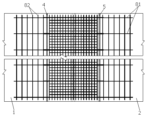
[0028] Figure 1-4 The shown flexible connection structure of the new and old bridges is used to connect the adjacent ends of the new bridge body 1 and the old bridge body 2; the new bridge body 1 and the old bridge body 2 have gaps 3 between the adjacent ends; A first groove is provided on the upper part of the old bridge body 2 adjacent to the new bridge body 1, and a first break 4 is provided on the first groove; the upper part of the...


PUM


Abstract

The invention discloses a stable and durable flexible connecting structure for old and new bridges and a construction method of the flexible connecting structure. The flexible connecting structure isused for connecting the two adjacent ends of a new bridge body and an old bridge body; a spacing seam exists between the two adjacent ends of the new bridge body and the old bridge body; the upper portion of the end, adjacent to the new bridge body, of the old bridge body is provided with first grooves, and the first grooves are provided with first breaking joints; the upper portion of the end, adjacent to the old bridge body, of the new bridge body is provided with second grooves, and the second grooves are provided with second breaking joints; the flexible connecting structure of the old andnew bridges comprises an isolation layer in lap joint on the first grooves and the second grooves, a lower densified rebar net arranged at the upper end of the isolation layer, a connecting rebar net, an upper densified rebar net arranged at the upper end of the connecting rebar net, concrete layers and an asphalt bridge floor; and the connecting rebar net is arranged at the upper end of the lower densified rebar net, the two ends of the connecting rebar net penetrate through the first breaking joints and the second breaking joints correspondingly, the first grooves and the second grooves arefilled with the concrete layers, and the asphalt bridge floor is laid at the upper ends of the old bridge body and the new bridge body.

Description

Technical field [0001] The invention relates to the technical field of road construction, in particular to a flexible connection structure of new and old bridges and a construction method thereof. Background technique [0002] Since the reform and opening up, my country's highway and municipal road construction has achieved rapid development, which has played an important role in the rapid development of the national economy. In recent years, with the continuous progress of society and the rapid economic development, some of the highways and municipal roads constructed in the early stage have been shown due to the narrow road width and fewer lanes, especially the two-way two- and four-lane highways and municipal roads. Due to traffic congestion and insufficient transportation capacity, road traffic capacity and service levels have decreased, and safety accidents have increased year by year. It has been unable to meet the needs of social development and urban and rural constructio...

Claims


Application Information

Patent Timeline
IPC IPC(8): E01D19/06E01D21/00
CPCE01D19/06E01D21/00
Inventor 卢三平李聪林陈长征周昆户东阳周小杨曾敏喻燕平杨业新陈国杰何清苏翌周小壮贺坤龙谢建科
Owner KUNMING SURVEY DESIGN & RES INST OF CREEC
Learn More