Semi-inclusion direct surface-mounting ground stress relief test device and method

A testing device and geostress technology, applied in measurement devices, force/torque/work measuring instruments, force sensors in holes of stressed structures, etc., can solve the uncertainty of test results, increase test links, and reduce measurement Accuracy and other issues, to achieve the effect of accurate compensation, ensuring accurate installation and installation accuracy, and eliminating measurement errors

Active Publication Date: 2018-08-17
CHANGJIANG RIVER SCI RES INST CHANGJIANG WATER RESOURCES COMMISSION
View PDF11 Cites 8 Cited by
  • Summary
  • Abstract
  • Description
  • Claims
  • Application Information

AI Technical Summary

Problems solved by technology

However, it has the following limitations: Compared with the direct patch technology, the hollow inclusion test increases the stress-strain transfer link of the glue layer and the epoxy resin layer, and adds 4 calculation parameters to obtain the analytical results
Therefore, this technology increases the testing process and reduces the measurement accuracy, which makes the test results have certain uncertainties.

Method used


Image

  • Semi-inclusion direct surface-mounting ground stress relief test device and method
  • Semi-inclusion direct surface-mounting ground stress relief test device and method
  • Semi-inclusion direct surface-mounting ground stress relief test device and method

Examples


Embodiment Construction

[0034] The technical solutions in the present invention will be clearly and completely described below in conjunction with the accompanying drawings in the present invention.

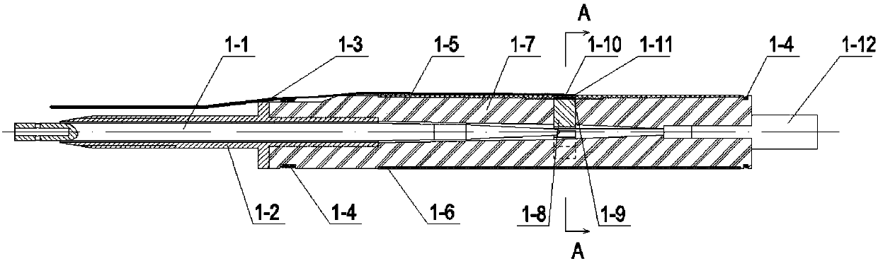
[0035] see figure 1 and figure 2 One embodiment of the semi-enclosed direct patch stress relief test device of the present invention includes a bracket 1-2, a support 1-7 connected to the bracket 1-2, and a rubber tube 1 sleeved on the periphery of the support 1-7 -6, the rubber tube 1-6 is provided with an opening for installing the strain cluster, and is bonded with the non-deformable layer 1-9.

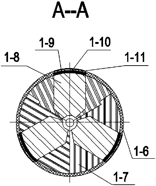
[0036] The support 1-7 is formed by splicing at least 3 arc-shaped blocks, and each arc-shaped block is provided with a quadrilateral slot from the inner hole to the outer surface, for installing the strain cluster push block 1-8, the non-deformable layer 1 -9 etc. The appearance of the strain cluster push block 1-8 is also an arc structure, and a plurality of arc blocks and the strain cluster push block 1...


PUM


Abstract

The invention provides a semi-inclusion direct surface-mounting ground stress relief test device and method. According to the device and method, measuring errors of stress-strain transmission, broughtby an inclusion layer and an adhesive layer of a hollow inclusion type strain gauge are eliminated, and a waterproof protection function of strain foils and lines by the strain gauge is reserved. Thedevice comprises a support, a support member connected with the support, and a rubber cylinder arranged at the periphery of the support member in a sleeved manner, the support member is formed by splicing of at least 3 arc blocks, each arc block is provided with a groove hole for installing a strain bundle push block from an inner bore to an exterior, the exterior of the strain bundle push blockis an arc structure, the plurality of arc blocks and the strain bundle push blocks are spliced to form a cylinder structure, and the rubber cylinder is arranged on an outer wall of the cylinder structure formed by the support member and the strain bundle push blocks in a sleeved manner. An outer end wall of each strain bundle push block is provided with a non-deformation layer, the rubber cylinderis provided with an opening for installing a strain bundle, and the non-deformation layer and the opening of the rubber cylinder are bonded; and a compensating gauge or a temperature sensor is bondedto the non-deformation layer, and strain bundle rubber and the strain bundle are bonded thereon in sequence.

Description

technical field [0001] The invention relates to the technical field of stress measurement for three-dimensional hole wall strain relief, in particular to a stress relief testing device and method for semi-included direct patching. Background technique [0002] The hole wall strain relief method is currently one of the most widely used methods for in-situ stress measurement in large-scale underground projects in industries such as water conservancy, hydropower, transportation, nuclear power, and mining. This method is the only measurement method that can give a three-dimensional stress state in a single test. So far, the hole wall strain testing techniques that have appeared include direct patch, hollow inclusion, rigid inclusion and solid inclusion. The direct mount technology has appeared successively since the 1960s, represented by the successful development of the "CSIR triaxial hole wall strain gauge" in South Africa. This method is one of the in-situ stress test method...

Claims


Application Information

Patent Timeline
Patent Type & Authority Applications(China)
IPC IPC(8): G01L5/00G01L1/04G01L1/06
CPCG01L1/04G01L1/06G01L5/0004Y02A10/23
Inventor 韩晓玉刘元坤尹健民周春华李永松李强邬爱清李玫付平曾平董志宏张新辉
Owner CHANGJIANG RIVER SCI RES INST CHANGJIANG WATER RESOURCES COMMISSION
Why Eureka
Try Eureka