
F-theta lens unit

A lens and lens technology, applied in the optical field, can solve the problem that F-Theta cannot meet the drilling requirements, and achieve the effect of uniform size, no tool loss and good economic benefits.

Pending Publication Date: 2018-08-17
NANJING WAVELENGTH OPTO ELECTRONICS SCI & TECH CO LTD
View PDF3 Cites 4 Cited by
  • Summary
  • Abstract
  • Description
  • Claims
  • Application Information

AI Technical Summary

Problems solved by technology

[0005] In order to solve the defects that F-Theta cannot meet drilling requirements in the prior art, the present invention provides an F-Theta lens

Method used


Image

  • F-theta lens unit
  • F-theta lens unit
  • F-theta lens unit

Examples


Embodiment 1

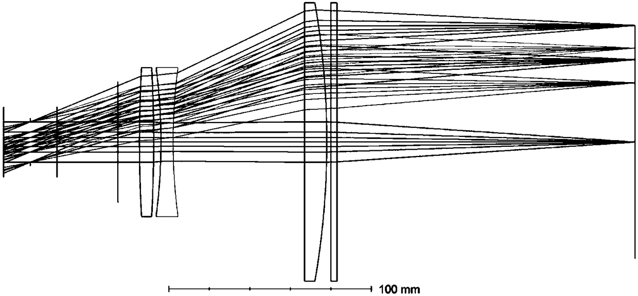
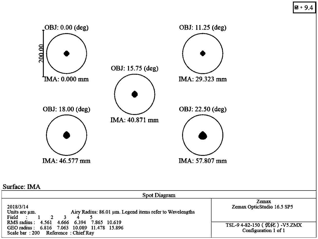
[0033] like Figure 8 Shown: an F-Theta lens, including a first lens, a second lens, a third lens and a window set in sequence along the light incident direction, the first lens is a positive lens, the second lens is a negative lens, and the third lens is a positive lens; Figure 8 Among them, the realization part parallel to the first lens, the second lens, the third lens and the window plate is the stepped outline of the inner surface of the mirror holder except for various pressure rings, gaskets and transition rings;

[0034] The first lens includes opposite first and second curved surfaces, the radius of curvature of the first curved surface is 680 mm, the radius of curvature of the second curved surface is 680 mm, and the central thickness of the first lens is 7 mm; the second lens includes an opposite third curved surface and the fourth curved surface, the radius of curvature of the third curved surface is -282mm, the radius of curvature of the second curved surface is...


PUM


Abstract

The invention discloses an F-theta lens unit, comprising a first lens, a second lens, a third lens and a window piece arranged sequentially along a light incoming direction. The first lens is a positive lens, the second lens is a negative lens, and the third lens is a positive lens. The F-theta lens unit is applicable to drilling, can meet various drilling requirements, is particularly suitable for the manufacture of small-diameter holes, and is suitable for processing of holes high in roundness and good in size uniformity.

Description

technical field [0001] The invention relates to an F-Theta lens (also referred to as a scanning lens or a field lens, hereinafter referred to as a field lens), which is mainly used in drilling of PCBs and belongs to the field of optics. Background technique [0002] The field mirror is an optical scanning focusing lens used in conjunction with the galvanometer. After adjusting the incident angle of the large-diameter beam incident on the galvanometer, the incident angle is adjusted by the mirror of the galvanometer, and then focused on the surface of the workpiece to realize the workpiece within a specific range. Drilling, welding, cutting, marking, internal carving and other processing operations. [0003] The main technical parameters of the field lens include: laser wavelength, focal length (FFL), scanning range, flange distance (BFL), working distance (WD) and incident spot diameter, etc.; parameters associated with the galvanometer include: XY two mirrors The center di...

Claims


Application Information

Patent Timeline
Patent Type & Authority Applications(China)
IPC IPC(8): G02B13/00G02B1/00
CPCG02B13/0005G02B1/00
Inventor 王坚韦晨曦朱敏吴玉堂
Owner NANJING WAVELENGTH OPTO ELECTRONICS SCI & TECH CO LTD
Learn More