
Luminescent device and display substrate

A light-emitting device and light-emitting layer technology, which is applied in the manufacture of electric solid-state devices, semiconductor devices, semiconductor/solid-state devices, etc., can solve the problem of small viewing angle of the display substrate, and achieve the effect of improving color purity and light extraction efficiency

Inactive Publication Date: 2018-08-17
BOE TECH GRP CO LTD
View PDF6 Cites 5 Cited by
  • Summary
  • Abstract
  • Description
  • Claims
  • Application Information

AI Technical Summary

Problems solved by technology

[0005] The present invention at least partially solves the problem that the viewing angle of the existing organic light emitting diode display substrate with a resonant cavity is small, and provides a light-emitting device and a display substrate that can form a resonant cavity and have a better viewing angle range

Method used


Image

  • Luminescent device and display substrate
  • Luminescent device and display substrate
  • Luminescent device and display substrate

Examples


Embodiment 1

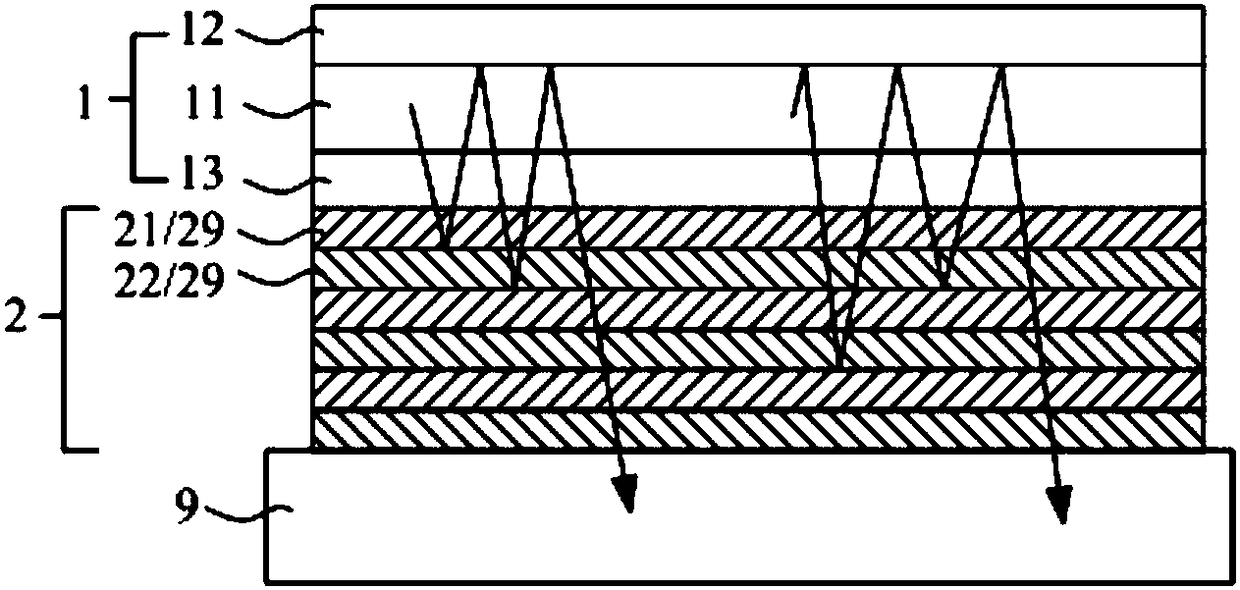
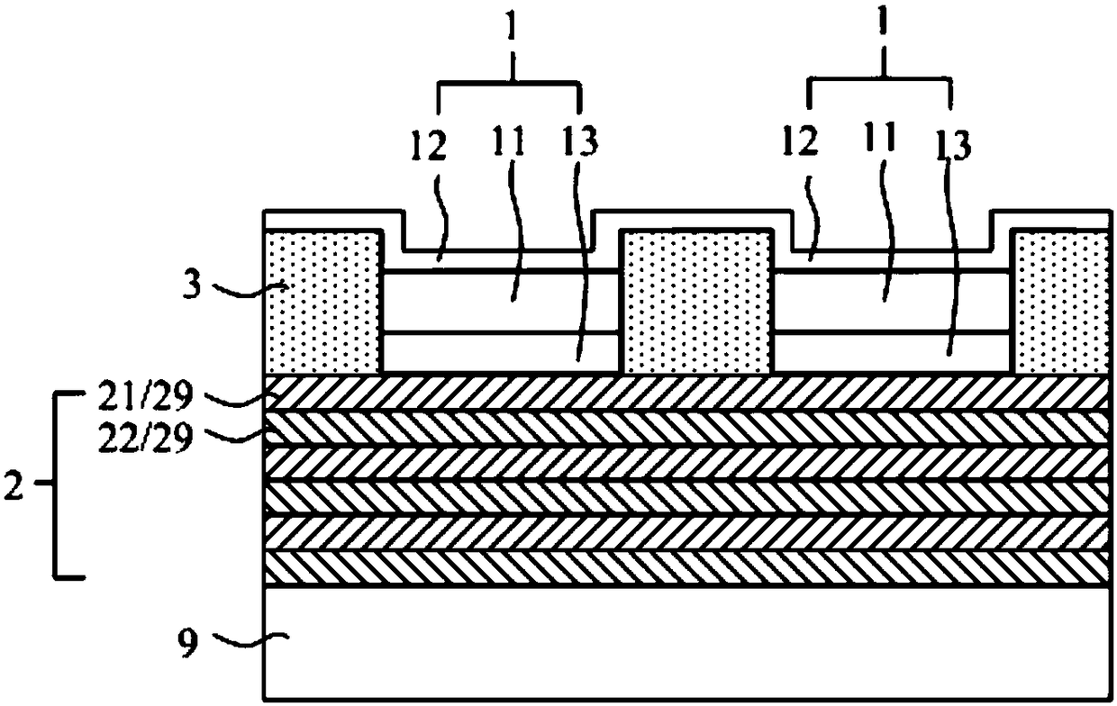
[0032] Such as Figure 2 to Figure 4 As shown, this embodiment provides a light-emitting device, including an organic light-emitting diode 1. The organic light-emitting diode 1 includes a stacked cathode 12, a light-emitting layer 11, and an anode 13, and one side thereof is a reflective side capable of reflecting light, and the other side for the light-emitting side.

[0033] The above light-emitting devices refer to devices with light-emitting functions, including organic light-emitting diodes 1 (OLEDs), so they are organic light-emitting diode light-emitting devices, which can be used in display substrates or as independent light sources.

[0034] In the organic light emitting diode 1 above, there are conventional cathode 12 , light emitting layer 11 , anode 13 and other structures, and these structures can be arranged on the substrate 9 . Wherein, the light-emitting layer 11 may include known layered structures such as an electron injection layer, an electron transport la...

Embodiment 2

[0069] This embodiment provides a display panel, which includes the above-mentioned display substrate.

[0070] That is to say, the above display substrate can be combined with the box-matching substrate to form a display panel with basic display capabilities.

[0071] This embodiment also provides a display device, which includes the above-mentioned display panel.

[0072] That is to say, the above display panel can be combined with other components such as a power supply and a housing to form a display device with a complete display function.

[0073] Specifically, the display device is an organic light emitting diode display device, which can be any product or component with a display function such as electronic paper, mobile phone, tablet computer, television, monitor, notebook computer, digital photo frame, and navigator.


PUM


Abstract

The invention provides a luminescent device and a display substrate, and belongs to the technical field of an organic light-emitting diode. The luminescent device and the display substrate can at least partially solve the problem that a current organic light-emitting diode display substrate with a resonant cavity has a smaller visual angle. The luminescent device includes an organic light-emittingdiode, wherein the organic light-emitting diode includes stacked cathode, luminescent layer and anode; and one side of the organic light-emitting diode is a reflection side being able to reflect light, and the other side of the organic light-emitting diode is a light emergent side. The luminescent device also includes a functional layer group which is arranged outside the light emergent side of the organic light-emitting diode, wherein the functional layer group is formed by a plurality of stacked functional layers; each functional layer is transparent; and any two adjacent functional layershave different refractive index.

Description

technical field [0001] The invention belongs to the technical field of organic light emitting diodes, and in particular relates to a light emitting device and a display substrate. Background technique [0002] Such as figure 1 As shown, in an organic light emitting diode (OLED) display substrate, each sub-pixel is provided with an organic light emitting diode 1 for emitting light. Since the display substrate generally only needs to emit light from one side, one side of the organic light emitting diode 1 can be set as the light emitting side with light reflection function (such as the cathode 12 itself of reflective material such as aluminum as a light reflection layer), for emitting light from the light emitting layer 22. The light is reflected to the light exit side (such as the side where the anode 13 of a transparent material such as indium tin oxide is located) and concentratedly emitted. [0003] The organic light emitting diode display substrate is affected by the re...

Claims


Application Information

Patent Timeline
IPC IPC(8): H01L51/50H01L51/52H01L27/32
CPCH10K59/00H10K50/00H10K50/852
Inventor 高昊
Owner BOE TECH GRP CO LTD
Learn More