Eureka AIR delivers breakthrough ideas for toughest innovation challenges, trusted by R&D personnel around the world.

Electroplating pretreatment oil fouling recycling basin

A technology for electroplating pretreatment and oil pollution recovery. It is used in metallurgical wastewater treatment, grease/oily substance/float removal devices, and liquid separation. It can solve the problems of limited treatment area, low efficiency, and poor working environment, and achieve efficient transfer. , high separation efficiency, improve the effect of layering efficiency

Pending Publication Date: 2018-08-21
江苏宏力环境工程科技有限公司
View PDF7 Cites 1 Cited by
  • Summary
  • Abstract
  • Description
  • Claims
  • Application Information

AI Technical Summary

Problems solved by technology

[0002] In the electroplating such as barrel plating or rack plating, or the electrochemical polishing process, before the electroplating or electrolytic polishing process, the product often has oil stains in the operation process and maintenance process, which seriously affects the quality of electroplating or polishing, so it needs to be cleaned
Usually, the workpiece is placed in a cleaning tank filled with water for hot-dip degreasing, ultrasonic degreasing, etc. After cleaning, a large amount of oily wastewater is generated, and direct discharge is not conducive to environmental protection and water conservation.
If the oil and water are not separated in time, it will affect the reuse of waste water
At present, manual separation is mostly used, and the efficiency of manual separation is low, and the working environment is poor; mechanical separation mostly uses a high-speed rotating disc oil scraper. Due to the limited processing area, the efficiency is relatively low and the power consumption is relatively high.

Method used


Image

  • Electroplating pretreatment oil fouling recycling basin
  • Electroplating pretreatment oil fouling recycling basin
  • Electroplating pretreatment oil fouling recycling basin

Examples


Embodiment 1

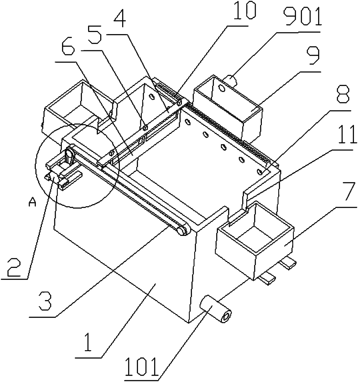
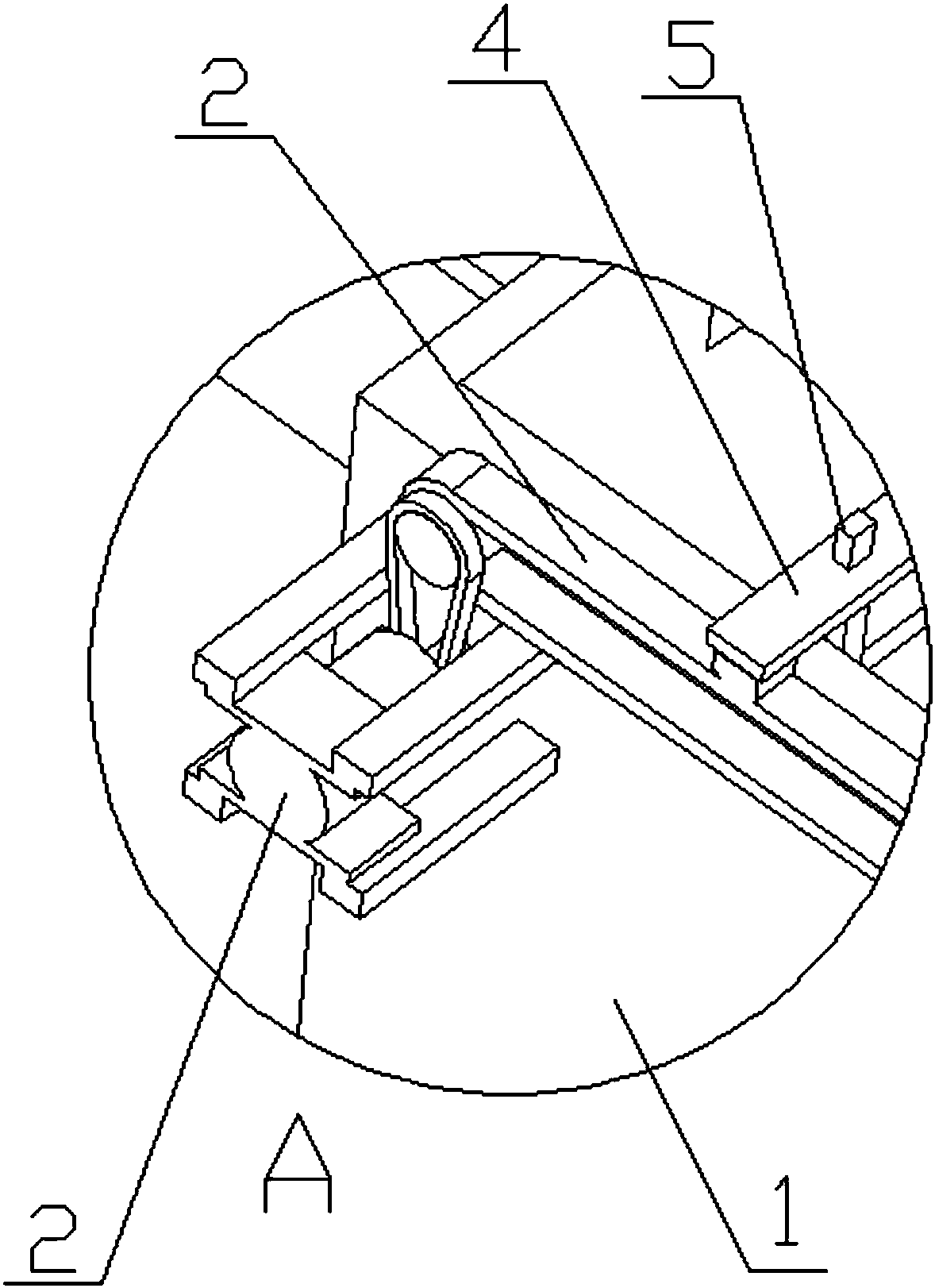
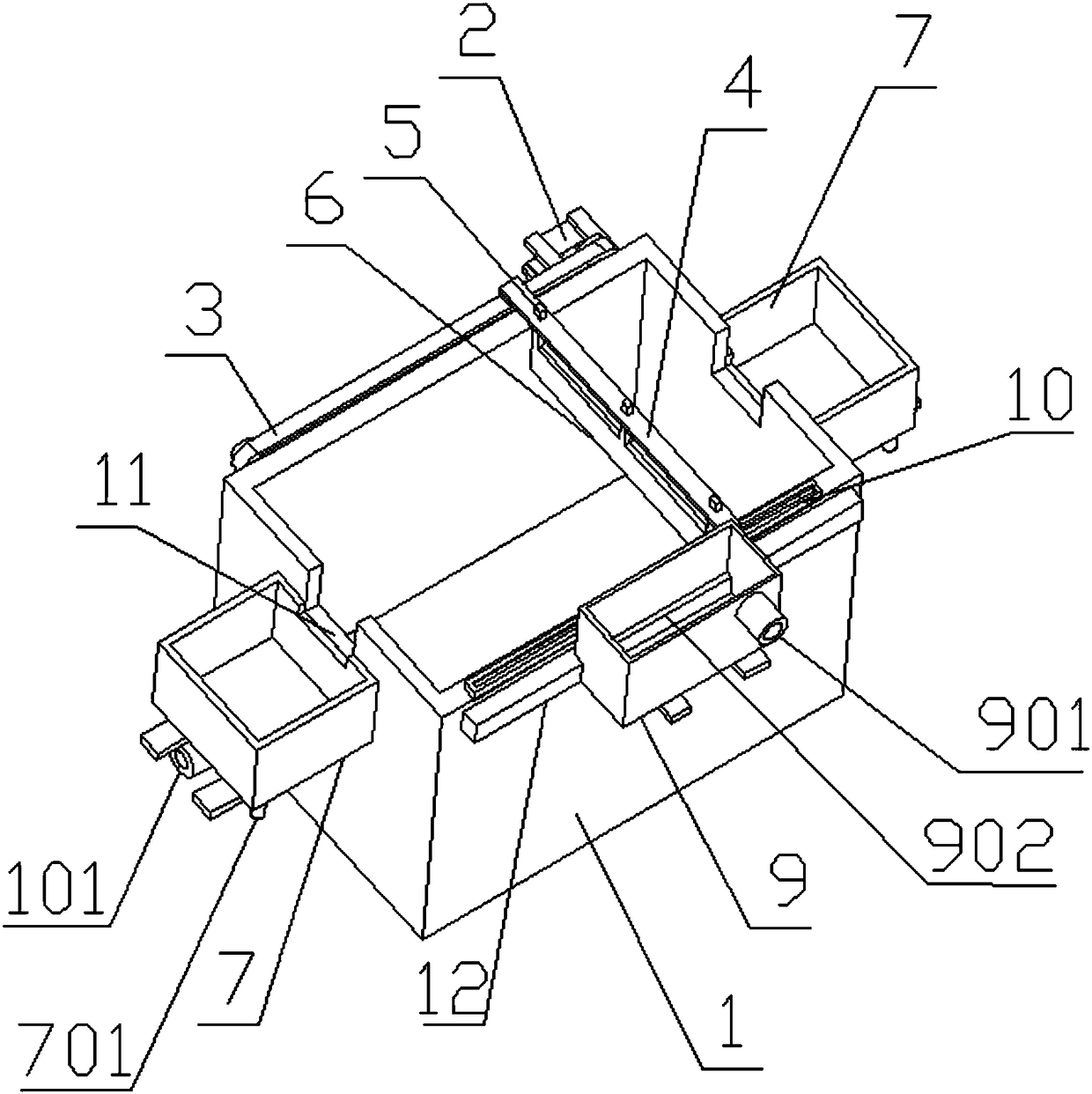
[0022] Such as Figure 1-4 Shown: 1. A pre-plating oil recovery tank, including a separation tank 1, an input system, and an oil layer transfer system. In the separation tank 1, due to different densities, oil and water will be separated, so the improvement points focus on quickly dissolving The oil layer is transferred to other spaces.

[0023] The separation tank 1 is a pool structure with no cover on the top and a rectangular cross-section. Two notch-shaped oil guide ports 11 are symmetrically distributed on the left and right sides of the separation tank 1 in the length direction. The side near the oil guide port 11 is installed with a bracket Oil storage tank 7, the upper part of the oil storage tank 7 is open, the top of the oil storage tank 7 is lower than the bottom of the oil guide port 11, and the oil storage tank 7 is close to the side of the separation pool 1, and the lower part of the oil storage tank 7 is provided with an oil outlet pipe 701; There is a water ou...

Embodiment 2

[0031] Other mechanisms are the same as in Embodiment 1, except the following aspects,

[0032] The filter screen 902 net mouth diameter is 8MM, the conveyor belt 3 is 300MM shorter than the length of the pool, the thickness of the oil-repelling plate 6 is 15MM, and the width of the oil-repelling plate 6 is 150MM. There is a 10MM gap between the oil-repelling plate 6 and the inner wall of the separation tank 1, the bottom of the oil-repelling plate 6 goes deep into the liquid surface 18MM, and the oil-repelling plate 6 is installed below the cross bar 4 by 4 adjustable vertical rods 5.

[0033] In summary, the present invention can quickly separate the oil stains generated by cleaning workpieces before electroplating through fully automatic operation, which is beneficial to the recycling of oil and water.


PUM

PropertyMeasurementUnit
widthaaaaaaaaaa

Abstract

The invention belongs to the technical field of electroplating, and particularly relates to an electroplating pretreatment oil fouling recycling basin. The electroplating pretreatment oil fouling recycling basin comprises a separation basin, an input system and oil layer transferring systems, wherein the separation basin is of an upper-cover-free pool structure having a rectangular section; two gap-shaped oil guide ports are symmetrically distributed on the left and right sides in the lengthwise direction of the separation basin; oil storage tanks are mounted on the side surfaces close to theoil guide ports through brackets; oil discharging pipes are arranged at the lower parts of the oil storage tanks; a water discharging pipe is arranged at the lower part of the side surface of the separation basin; clean water can be discharged from the water discharging pipe; the input system is mounted above the rear side surface of the separation basin through a bracket; the input system filtersout impurities such as solid particles in oil fouling and uniformly conveys the impurities to the liquid level of the separation basin; the oil layer transferring systems are mounted on the front side surface and the top surface of the separation basin; and the oil layer transferring systems can transfer oil layers to the oil storage tanks through reciprocating motion. The electroplating pretreatment oil fouling recycling basin disclosed by the invention can quickly separate the oil fouling produced by cleaning a workpiece before electroplating through full-automatic operation, and is favorable for recycling utilization of oil and water.

Description

technical field [0001] The invention belongs to the field of electroplating, and in particular relates to an oil pollution recovery pool for pre-electroplating treatment. Background technique [0002] During electroplating such as barrel plating or rack plating, or electrochemical polishing process, before the electroplating or electrolytic polishing process, the product often has oil stains from the operation process and maintenance process, which seriously affects the quality of electroplating or polishing, so it needs to be cleaned. Usually, the workpiece is placed in a cleaning tank filled with water for hot-dip degreasing, ultrasonic degreasing and other treatments. After cleaning, a large amount of oily wastewater will be generated, and direct discharge is not conducive to environmental protection and water conservation. If the oil and water are not separated in time, the reuse of waste water will be affected. At present, manual separation is mostly used, and the effi...

Claims


Application Information

Patent Timeline
Patent Type & Authority Applications(China)
IPC IPC(8): C02F1/40C02F103/16
CPCC02F1/40C02F2103/16
Inventor 孙玉明张国娟
Owner 江苏宏力环境工程科技有限公司
Why Eureka
Eureka Blog
Learn More