
An in-situ treatment and purification device for polluted rivers

An in-situ treatment and purification device technology, which is applied in the field of polluted water treatment, can solve the problems of difficult growth and reproduction of microorganisms, limited purification capacity, and water flow washing away the purification system, etc., and achieves the functions that are conducive to growth and reproduction, not easy to impact loss, and oxidation Guaranteed effect

Active Publication Date: 2021-04-27
ANHUI POLYTECHNIC UNIV
View PDF5 Cites 0 Cited by
  • Summary
  • Abstract
  • Description
  • Claims
  • Application Information

AI Technical Summary

Problems solved by technology

In the existing purification technology, a purification system is arranged in the entire width of the river to achieve a certain purification effect, but it is not conducive to the passage of ships and the flood discharge during the flood period. During the flood period, due to the large increase in water flow, the content of nutrients such as nitrogen and phosphorus in the water body The water quality is relatively good. At this time, the river channel should give full play to the function of flood discharge. During the flood period, the water flow increases greatly and there is a risk of destroying the purification system. There are also scattered water purification equipment, but the purification capacity is limited and cannot It can well guarantee the purification effect of micro-polluted water bodies in urban rivers during non-flood periods
The purification system generally includes a sedimentation module, a microbial oxidation module, and an aquatic animal and plant purification module. In the application of the microbial oxidation module, if the water flow rate is fast, the microorganisms are not easy to grow and reproduce, and the grown microorganisms are easily lost by impact, resulting in microbial oxidation. Unstable function

Method used


Image

  • An in-situ treatment and purification device for polluted rivers
  • An in-situ treatment and purification device for polluted rivers
  • An in-situ treatment and purification device for polluted rivers

Examples


Embodiment

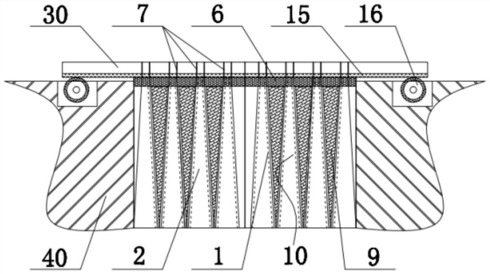
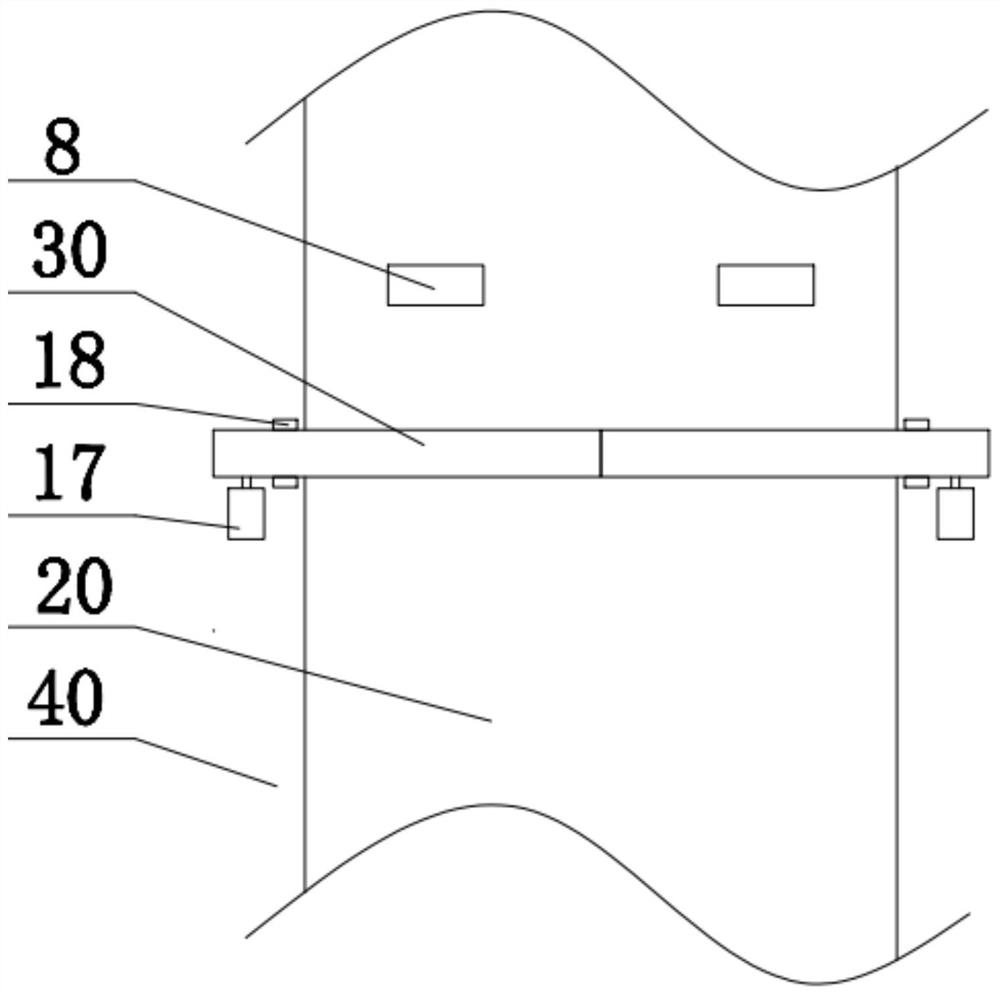
[0027] An in-situ treatment and purification device for polluted rivers, such as figure 1 As shown, it includes two installation rods 30 arranged in the width direction of the horizontal channel and a purification mechanism installed under the installation rods 30. The wall 10 and the microbial oxidation net 9 arranged between every two adjacent protective backboards 2,

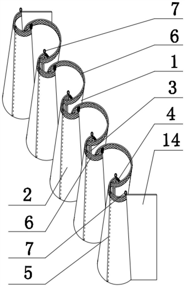
[0028] The protective front plate 1 is located on the front side of the sedimentation filter wall 10 facing the water flow direction, and the protective back plate 2 is located on the rear side of the sedimentation filter wall 10 facing the water flow direction, as image 3 As shown, the protective front plate 1 is an arc-shaped plate that gradually decreases from top to bottom, and the protective rear plate 2 is an arc-shaped plate that gradually increases from top to bottom, and the protective front plate 1 and the protective rear plate 2 The inner arc side is oppositely arranged, and the left and right si...


PUM


Abstract

The invention discloses an in-situ treatment and purification device for polluted rivers, which belongs to the field of polluted water treatment and comprises a purification mechanism installed under a mounting rod. The microbial oxidation network is arranged between every adjacent two protective back plates. The top of the protective front plate and the protective rear plate are equipped with floating bodies. There are water holes on the left and right sides, and the middle part of the protective back plate is provided with a longitudinal shaft. Mount on pole. The invention can comprehensively control the water body without affecting sailing and flood discharge, can carry out sedimentation and microbial oxidation on the water body, can effectively prevent the growth and reproduction of microorganisms, and ensure the stability of the microbial oxidation function.

Description

technical field [0001] The invention relates to the field of polluted water treatment, in particular to an in-situ treatment and purification device for polluted river courses. Background technique [0002] At present, with the continuous expansion of urban areas, rivers that originally had the function of purification have lost their function, and a large number of urban rivers have evolved into stormwater channels and even sewers. This is a concentrated expression of the lack of urban infrastructure and the imperfection of the pipe network, which eventually causes a large amount of pollution in the urban water body and the surrounding environment deteriorates significantly. [0003] The water flow of urban rivers, in the non-flood period, is mainly polluted by domestic sewage and excrement, which often contain nutrients such as nitrogen and phosphorus, and generally does not contain toxic substances, and belongs to slightly polluted water bodies. In the existing purificat...

Claims


Application Information

Patent Timeline
Patent Type & Authority Patents(China)
IPC IPC(8): C02F9/14
CPCC02F1/001C02F3/34C02F2001/007C02F2103/007
Inventor 杨晓凡余丹妮张钰赵晨晨吴金健
Owner ANHUI POLYTECHNIC UNIV
Learn More