
Device for measuring hydration heat radiation velocity and hydration period of cement and use method of device

A heat release rate and cement hydration technology, which is applied to the device for measuring the heat release rate and hydration period of cement hydration, and in the field of cement concrete performance testing, can solve the problems of complex preparation, short continuous monitoring time, complicated operation, etc., and achieve The technical and economic benefits are obvious, the experimental equipment is portable, and the effect of avoiding particle stratification

Inactive Publication Date: 2018-08-21
SOUTHEAST UNIV
View PDF7 Cites 5 Cited by
  • Summary
  • Abstract
  • Description
  • Claims
  • Application Information

AI Technical Summary

Problems solved by technology

[0004] The existing technology mainly uses the Vicat instrument to measure the cement setting time and infer the hydration period, which has the disadvantages of large errors, complicated operations, and the inability to measure multiple samples at the same time and repeated measurements; the heat of hydration is mainly obtained through the solution heat method and thermal conduction isothermal The calorimeter has the disadvantages of complex preparation in the early stage, large errors, short continuous monitoring time, high instrument cost and inconvenient portability, and uneven distribution of cement samples after standing test.

Method used


Image

  • Device for measuring hydration heat radiation velocity and hydration period of cement and use method of device
  • Device for measuring hydration heat radiation velocity and hydration period of cement and use method of device
  • Device for measuring hydration heat radiation velocity and hydration period of cement and use method of device

Examples


Embodiment 1

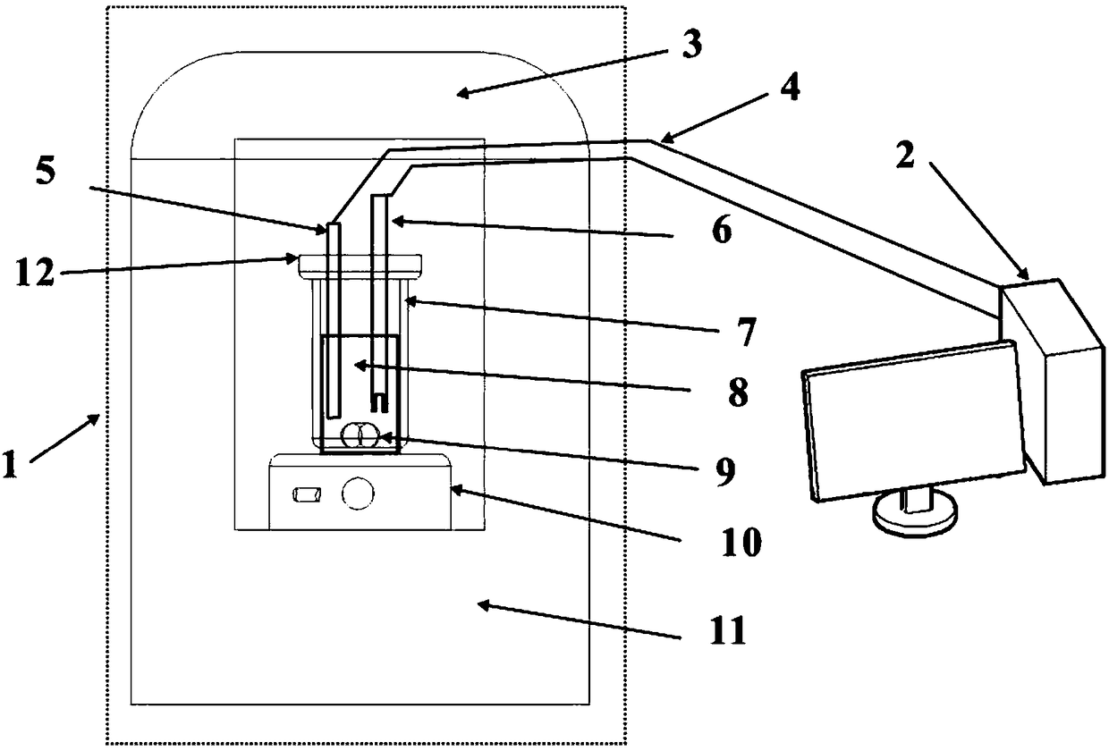
[0039] A device for measuring cement hydration heat release rate and hydration period, the device is composed of a test device 1 and a computer 2;

[0040] Wherein the testing device 1 comprises a heat preservation chamber 11 and a heat preservation chamber cover 3, both of which constitute a sealed environment, a sample chamber 7 is arranged inside the heat preservation chamber 11, an electromagnetic stirring device 10 and a sample pool 8 are arranged inside the sample chamber 7, and the electromagnetic stirring device 10 is located at the bottom of the inside of the sample chamber 7, the sample cell 8 is placed on the electromagnetic stirring device 10, and the upper opening of the sample cell 8 is sealed by a sealing cover 12, and the temperature sensor 5 and the conductivity sensor 6 are arranged through the sealing cover 12 , one end of the test point extends into the sample pool 8, the other end is respectively connected with a data line 4, and a stirring rotor 9 is place...

Embodiment 2

[0049] A device for measuring cement hydration heat release rate and hydration period, the device is composed of a test device 1 and a computer 2;

[0050] Wherein the testing device 1 comprises a heat preservation chamber 11 and a heat preservation chamber cover 3, both of which constitute a sealed environment, a sample chamber 7 is arranged inside the heat preservation chamber 11, an electromagnetic stirring device 10 and a sample pool 8 are arranged inside the sample chamber 7, and the electromagnetic stirring device 10 is located at the bottom of the inside of the sample chamber 7, the sample cell 8 is placed on the electromagnetic stirring device 10, and the upper opening of the sample cell 8 is sealed by a sealing cover 12, and the temperature sensor 5 and the conductivity sensor 6 are arranged through the sealing cover 12 , one end of the test point extends into the sample pool 8, the other end is respectively connected with a data line 4, and a stirring rotor 9 is place...

Embodiment 3

[0059] A device for measuring cement hydration heat release rate and hydration period, the device is composed of a test device 1 and a computer 2;

[0060] Wherein the testing device 1 comprises a heat preservation chamber 11 and a heat preservation chamber cover 3, both of which constitute a sealed environment, a sample chamber 7 is arranged inside the heat preservation chamber 11, an electromagnetic stirring device 10 and a sample pool 8 are arranged inside the sample chamber 7, and the electromagnetic stirring device 10 is located at the bottom of the inside of the sample chamber 7, the sample cell 8 is placed on the electromagnetic stirring device 10, and the upper opening of the sample cell 8 is sealed by a sealing cover 12, and the temperature sensor 5 and the conductivity sensor 6 are arranged through the sealing cover 12 , one end of the test point extends into the sample pool 8, the other end is respectively connected with a data line 4, and a stirring rotor 9 is place...


PUM

PropertyMeasurementUnit
thicknessaaaaaaaaaa

Abstract

The invention discloses a device for measuring the hydration heat radiation velocity and the hydration period of cement and a use method of the device. The device comprises a heat-preservation cabin and a heat-preservation cabin cover, wherein a sample cabin is arranged inside the heat-preservation cabin; an electromagnetic stirring device and a sample tank are arranged inside the sample cabin; the electromagnetic stirring device is positioned at the bottom end of the sample cabin; the sample tank is arranged on the electromagnetic stirring device; the sample tank is opened and can be conveniently sealed by using a sealing cover; a temperature sensor and an electric conductivity sensor are arranged on the sealing cover in a penetrating manner; a stirring rotor is arranged inside the sampletank; a computer is connected with the temperature sensor and the electric conductivity sensor through data wires. When the device is used, a sample is placed in the sample tank, the device is mounted, the electromagnetic stirring device is powered on, and temperature and electric conductivity variation curves are recorded by using the computer when a cement concrete slurry structure is formed. The device is capable of continuously, automatically and in-situ monitoring the whole structure formation process once water is added, and in addition, the experiment equipment is convenient to carry over and low in cost.

Description

technical field [0001] The invention relates to a device for measuring the heat release rate and hydration period of cement hydration and its use method, belonging to the cement concrete performance testing technology. Background technique [0002] Cement concrete is the most important building material today, widely used in construction, transportation, bridges, water conservancy, underground engineering and other fields. With the rapid development of the global economy and the unprecedented scale of construction, the use of cement concrete is increasing year by year, especially for China with rapid economic development; however, due to the complex components of modern concrete, the amount of cementitious materials is large, and a large amount of industrial waste is added And admixtures are easy to crack in the early stage, resulting in a decline in long-term mechanical strength and durability. In recent years, premature failure of concrete structures has occurred frequent...

Claims


Application Information

Patent Timeline
Patent Type & Authority Applications(China)
IPC IPC(8): G01N25/48G01N27/04
CPCG01N25/48G01N25/4813G01N27/04
Inventor 张云升逄博
Owner SOUTHEAST UNIV
Learn More