Machine vision technology-based laser structured light automatic calibration method

A laser structure and machine vision technology, applied in the field of visual recognition, can solve the problems of difficult selection of processing materials, low degree of automation of the calibration process, slow speed, etc., and achieve the effect of high reliability of the algorithm

Pending Publication Date: 2018-08-21
深圳市中捷视科科技有限公司
View PDF9 Cites 15 Cited by
  • Summary
  • Abstract
  • Description
  • Claims
  • Application Information

AI Technical Summary

Problems solved by technology

[0003] At present, the measurement structure accuracy of the general parameter analysis method laser structure cursor calibration method has low calibration accuracy, complex calculation, low degree of automation and slow speed of the calibration process, which cannot meet the needs of mass production of laser measurement devices; and these calibration methods need to be in accordance with To make a three-dimensional target, the processing technology of the three-dimensional target is complicated. For example, it is very difficult to process a high-precision tooth-shaped target, and it is also difficult to select processing materials. Metal parts are prone to rust when stored for a long time

Method used


Image

  • Machine vision technology-based laser structured light automatic calibration method
  • Machine vision technology-based laser structured light automatic calibration method
  • Machine vision technology-based laser structured light automatic calibration method

Examples


Embodiment Construction

[0056] The implementation of the present invention will be described in detail below in conjunction with the accompanying drawings and examples, so as to fully understand and implement the process of how to apply technical means to solve technical problems and achieve technical effects in the present invention. It should be noted that, as long as there is no conflict, each embodiment and each feature in each embodiment of the present invention can be combined with each other, and the formed technical solutions are all within the protection scope of the present invention.

[0057] In addition, the steps shown in the flow diagrams of the figures may be performed in a computer system, such as a set of computer-executable instructions, and, although a logical order is shown in the flow diagrams, in some cases, the sequence may be different. The steps shown or described are performed in the order herein.

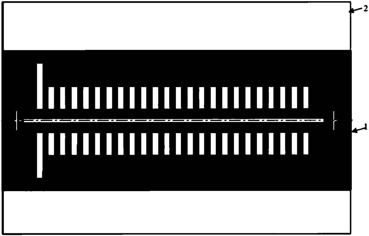
[0058] Specifically, the present invention uses a high-precision etched glas...


PUM


Abstract

The invention discloses a machine vision technology-based laser structured light automatic calibration method. The method comprises steps: 1) a calibration board is firstly placed at a clear imaging position; 2) the calibration plate is adjusted to a horizontal position; 3) the distances between a laser line emitted by the laser and cross marks at two sides of the calibration plate are adjusted tobe the minimum; 4) the laser is closed, a backlight source is opened, camera gains and the exposure time are adjusted, a printer marker on the calibration plate is photographed, and an image 1 is acquired; 5) the laser is opened, the backlight source is closed, a laser spot image is photographed, and an image 2 is acquired; and 6) the image 1 and the image 2 are fused to calculate the intersection point between the rectangular edge line of the calibration plate and the laser line.

Description

technical field [0001] The invention belongs to the field of visual recognition, and belongs to a laser structured light automatic calibration method based on machine vision technology. Background technique [0002] The line-structure laser scanning vision system is an important 3D imaging measurement method. It uses a line-shaped laser to project onto the surface of the object, and then the image sensor receives the laser spot image to complete the measurement process. The key to building a line-structure laser scanning vision system is to calibrate the spatial geometric relationship between the camera and the laser light plane. Duan Fajie et al. from Tianjin University used the tooth-shaped target method, using the laser line to irradiate the tooth-shaped target vertically, and then solved the iterative equation to calculate the perspective parameters of the light plane to complete the calibration. Dewar R uses the filament scattering method, also known as the drawing met...

Claims


Application Information

Patent Timeline
Patent Type & Authority Applications(China)
IPC IPC(8): G06T7/80
CPCG06T7/85G06T2207/10028G06T2207/30208
Inventor 王晓东苏翠芳
Owner 深圳市中捷视科科技有限公司
Why Eureka
Try Eureka