Motor stator, motor, linear motor stator and linear motor

A motor stator and linear motor technology, applied in the direction of electrical components, electromechanical devices, electric components, etc., can solve problems such as motor power increase, environmental noise pollution, structural size restrictions, etc., achieve reduced production costs, simple motor structure, and reduced production cost effect

Pending Publication Date: 2018-08-21
ZHUHAI ENPOWER ELECTRIC
View PDF6 Cites 5 Cited by
  • Summary
  • Abstract
  • Description
  • Claims
  • Application Information

AI Technical Summary

Problems solved by technology

[0003] The disadvantage of adding a gearbox is that it is large in size and heavy in weight, which reduces system efficiency and causes environmental noise pollution on site; while increasing the number of pole pairs increases the technical difficulty of offline and wiring in the case of three-phase or multi-phase, the process The cost has risen sharply, and the upper limit of the number of pole pairs is strictly limited by the structural size. Under the same torque condition, the power of the motor needs to be greatly increased

Method used


Image

  • Motor stator, motor, linear motor stator and linear motor
  • Motor stator, motor, linear motor stator and linear motor
  • Motor stator, motor, linear motor stator and linear motor

Examples


no. 1 example

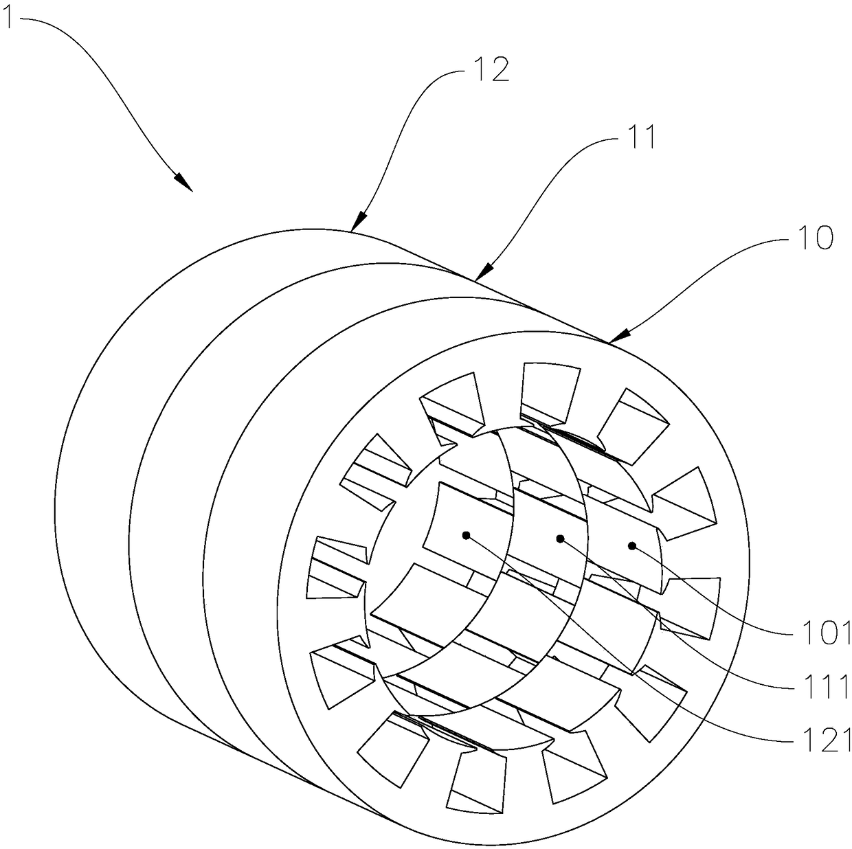
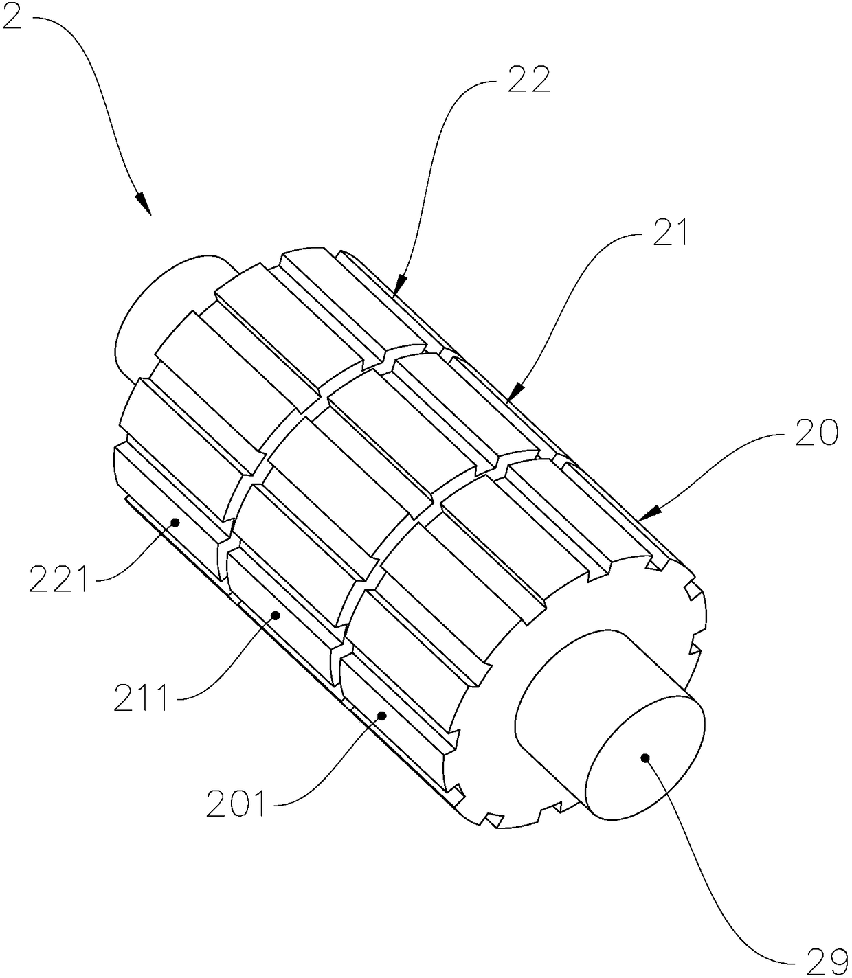
[0042] see figure 1 with figure 2 , figure 1 It is a structural schematic diagram of the hidden Hall device and winding of the motor stator in the first embodiment of the motor of the present invention, figure 2 It is a structural schematic diagram of the motor rotor in the first embodiment of the motor of the present invention. The motor of this embodiment is formed by coaxially laminating three motor units, and each motor unit includes a stator unit and a rotor unit that cooperate with each other. Correspondingly, the motor stator 1 includes three coaxially fixed stator units, and the motor rotor 2 Consists of three mover units coaxially fixed.

[0043] combine Figure 5 , Figure 5 It is a structural schematic diagram of the motor unit in the first embodiment of the motor of the present invention. In order to facilitate the description of the structure of the motor stator 1, the Hall device and the winding on the electronic core are in figure 1 hidden in . The mot...

no. 2 example

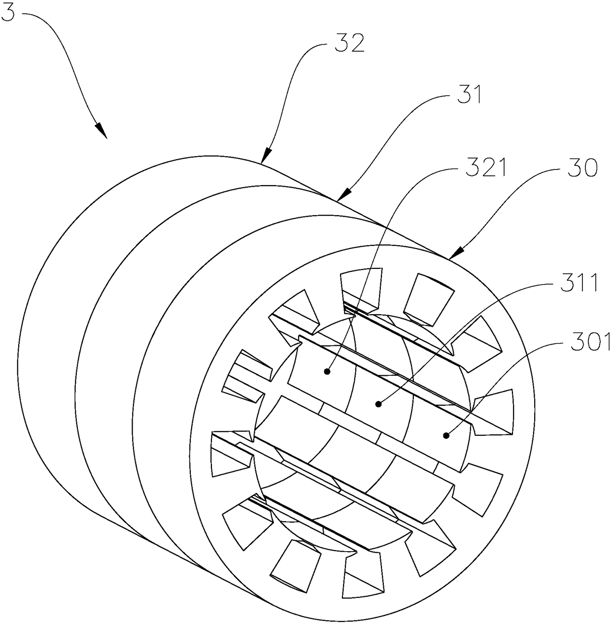
[0055] see image 3 with Figure 4 , image 3 It is a structural schematic diagram of some components hidden in the stator of the motor in the second embodiment of the motor of the present invention. Figure 4 It is a structural schematic diagram of the motor rotor in the second embodiment of the motor of the present invention. Optionally, the mechanical deflection angle a between the motor units can be realized only by the deflection angles between a plurality of rotor units in the motor rotor. On the axial projection of the motor stator 3 , the teeth 301 of the stator unit 30 , the teeth 311 of the stator unit 31 and the teeth 321 of the stator unit 32 overlap and align with each other without an off-angle. On the axial projection of the motor rotor 4, there is a mechanical deflection angle a between the permanent magnet 401 of the rotor unit 40 and the permanent magnet 411 on the rotor unit 41, and the permanent magnet 421 on the rotor unit 42 and the permanent magnet 41...


PUM


Abstract

The invention provides a motor stator, a motor, a linear motor stator and a linear motor. The motor includes n coaxial motor units. The motor unit includes a rotor unit and a stator unit. The numbersof rotor magnetic poles and stator poles are both n. A mechanical deflection angle is arranged between adjacent motor units. The mechanical deflection angle a=360/(n*m) degrees. The polarities of theadjacent rotor magnetic poles are opposite; a Hall element is arranged between adjacent stator magnetic poles. The linear motor comprises n motor units arranged side by side along the Y-axis direction, wherein the motor unit comprises a rotor unit and a stator unit. The number of the stator magnetic poles is m. The number of the rotor magnetic poles is z. A Hall element is arranged on the stator unit every z-1 stator magnetic poles; the stator magnetic pole has a distance d. The rotor magnetic pole has a distance d. An offset h is arranged between adjacent motor units and the offset h=d/n. Both the motor and the linear motor have the characteristics of direct drive, low speed and large load output.

Description

technical field [0001] The invention relates to the field of motors, in particular to a motor stator, a motor, a linear motor stator and a linear motor. Background technique [0002] At present, there are two types of motors: asynchronous motor and synchronous motor. The stator of the motor is mostly designed according to the principle of three-phase or multi-phase rotating magnetic field, and the rotor is realized by the principle of permanent magnet, induction cage or reluctance. In actual use, if it is necessary to obtain low-speed high-torque output, it is necessary to increase the reduction box, or increase the number of pole pairs. [0003] The disadvantage of adding a gearbox is that it is large in size and heavy in weight, which reduces system efficiency and causes environmental noise pollution on site; while increasing the number of pole pairs increases the technical difficulty of offline and wiring in the case of three-phase or multi-phase, the process The cost ha...

Claims


Application Information

Patent Timeline
Patent Type & Authority Applications(China)
IPC IPC(8): H02K16/04H02K41/03H02K1/14H02K1/27
CPCH02K1/146H02K1/2773H02K16/04H02K41/031
Inventor 李红雨刘宏鑫
Owner ZHUHAI ENPOWER ELECTRIC
Why Eureka
Try Eureka