MOSFET isolation drive circuit

A technology for isolating drive circuits and capacitors, applied to electrical components, high-efficiency power electronics conversion, output power conversion devices, etc., can solve the problems of large signal delay time, increased loss, and increased turn-off speed changes, etc., to achieve reduction Effects of small turn-off loss, reliable turn-off, and accelerated turn-off

Pending Publication Date: 2018-08-21
FOSHAN POLYTECHNIC
View PDF0 Cites 3 Cited by
  • Summary
  • Abstract
  • Description
  • Claims
  • Application Information

AI Technical Summary

Problems solved by technology

The circuit is more complex than the direct drive, but the drive circuit is isolated from the switch tube and has anti-interference ability, but the anti-common mode interference ability is weak; due to the use of optocouplers, the signal delay time is large and the speed is slow, and the suspension power supply needs to be added at the same time
[0008] (3) Dedicated IC driver: use a dedicated integrated circuit module, including optocoupler, amplifier, overcurrent protection, etc., easy to use, simple circuit, but high cost
But there are the following disadvantages: First, the isolation transformer secondary needs a dummy load R2, which increases the loss; second, when the duty cycle changes, the turn-off speed changes greatly
When the driving pulse width is narrow, the turn-off speed of the MOSFET gate becomes slower due to the reduction of energy stored in the transformer

Method used


Image

  • MOSFET isolation drive circuit
  • MOSFET isolation drive circuit
  • MOSFET isolation drive circuit

Examples


Embodiment Construction

[0022] In order to make the object, technical solution and advantages of the present invention more clear and definite, the present invention will be further described in detail below with reference to the accompanying drawings and examples.

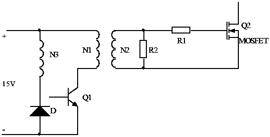
[0023] Such as figure 1 As shown, Q1 is the driving tube, N1 and N2 are the primary and secondary of the transformer respectively, N3 is the magnetic reset winding of the transformer, Q2 is the MOSFET to be driven; R1 is the damping resistor to prevent the voltage oscillation between the gate and the source, R2 is used to eliminate the possibility that Q2 may be disturbed and misconducted when the drive is 0, and at the same time it is used as a gate charge discharge circuit when the MOSFET is turned off. This is a forward drive circuit. When Q1 is turned off and after it is turned off, the secondary circuit of the transformer actually forms an LC damped oscillation between the secondary winding and the Q2 G-S capacitor, and the voltage ...


PUM


Abstract

The invention discloses an MOSFET isolation drive circuit. The MOSFET isolation drive circuit comprises a transformer winding, a triode Q1, a field-effect tube Q3, a triode Q2 and a capacitor C, wherein the triode Q1 is used for inputting a PWM control signal, the field-effect tube Q3 is connected with a secondary winding in the transformer winding, the triode Q2 is connected with a grid electrodeof the field-effect tube Q3, and the capacitor C is used for storing electricity during the breakover of the field-effect tube; two ends of a primary winding of the transformer winding are respectively connected with a collecting electrode and emitting electrode of the triode Q1; the primary winding of the transformer winding is also connected with a power supply; an emitting electrode of the triode Q1 is also connected with the ground; a G electrode and S electrode of the field-effect tube Q3 are respectively connected with two ends of the secondary winding in the transformer winding; a collecting electrode of the triode Q2 is connected with the G electrode of the field-effect tube Q3, a base electrode of the triode Q2 is connected with the other end of the secondary winding in the transformer winding; the capacitor C is respectively connected between the S electrode of the field-effect tube Q3 and an emitting electrode of the triode Q2.

Description

technical field [0001] The invention relates to the field of switching power supplies, in particular to a MOSFET isolation drive circuit. Background technique [0002] MOS field effect transistor (MOSFET) and insulated gate transistor (IGBT) have the advantages of small driving power, fast switching speed, and large power capacity, and are commonly used power switching devices for switching power supplies. [0003] The gate drive circuit of this type of device is very important, and the quality of the drive directly affects the reliability and performance indicators of the switching power supply. For example, the driving signal has a fast rising edge when it is turned on and should be able to provide a large enough charging current to make the voltage between the gate and source of the device rise rapidly, ensuring that the device is turned on quickly and there is no high-frequency oscillation of the rising edge; , the drive circuit can provide a path with as low impedance ...

Claims


Application Information

Patent Timeline
Patent Type & Authority Applications(China)
IPC IPC(8): H02M1/08
CPCH02M1/08H02M1/0054Y02B70/10
Inventor 林为
Owner FOSHAN POLYTECHNIC
Why Eureka
Try Eureka