Double motion freedom degree low thermal resistance locking device

A technology of locking device and degree of freedom, applied in clamping/extracting device, support structure installation, cooling/ventilation/heating transformation, etc., can solve the problem of weakening the ability of the wedge block to resist axial force and the inability of the LRM module to be pulled out from the chassis Problems such as increasing the thermal resistance of the contact surface, etc., to achieve the effect of increasing the number of contact surfaces, simplifying the technical solution, and reducing the heat transfer temperature difference

Active Publication Date: 2018-08-21
10TH RES INST OF CETC
View PDF3 Cites 6 Cited by
  • Summary
  • Abstract
  • Description
  • Claims
  • Application Information

AI Technical Summary

Problems solved by technology

Under a large locking force, if measures are not taken to enhance the hardness of the aluminum alloy surface, such as surface heat treatment, or the use of special coatings, the contact surface is easily crushed, especially under strong vibration conditions, resulting in jamming
Both heat treatment and surface coating lead to higher cost, and the coating usually increases the thermal resistance of the contact surface, thereby increasing the overall thermal resistance of the locking strip
[0008] 3. High thermal resistance
But the large size of the locking bar needs to occupy more space in the chassis, or requires a larger and heavier chassis
[0009] 4. Easy to get stuck
Due to the use of wedge-shaped locking blocks with a C-shaped cross-section, the cross-section of its open and thin-walled structure weakens the ability of the wedge blocks to resist axial force, and the matching parts between the wedge blocks are prone to plastic deformation under the action of axial force , the locking device is stuck, which makes the LRM module unable to be pulled out from the chassis

Method used


Image

  • Double motion freedom degree low thermal resistance locking device
  • Double motion freedom degree low thermal resistance locking device
  • Double motion freedom degree low thermal resistance locking device

Examples


Embodiment Construction

[0024] The present invention can be realized with reference to the following examples.

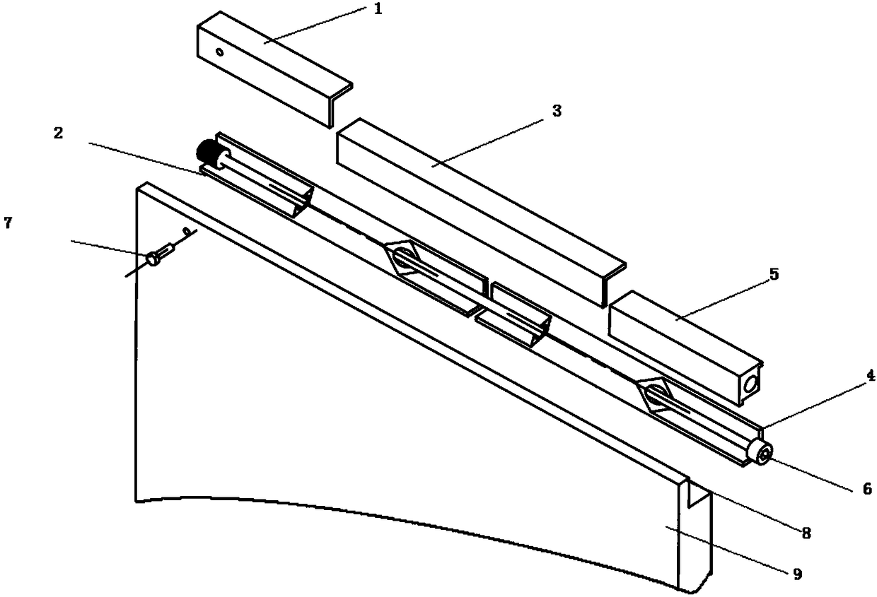
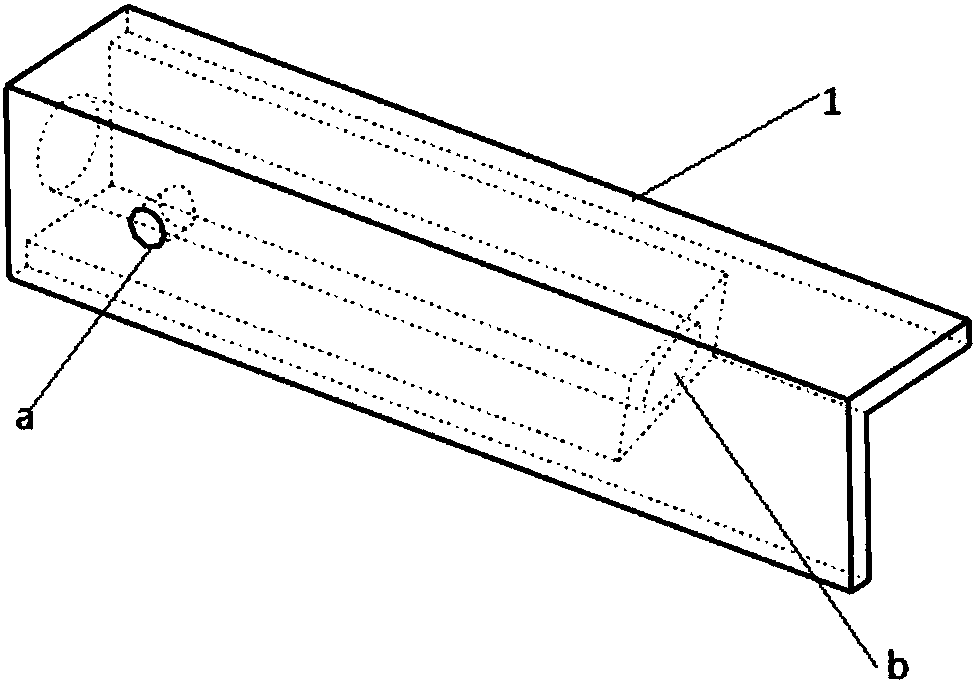
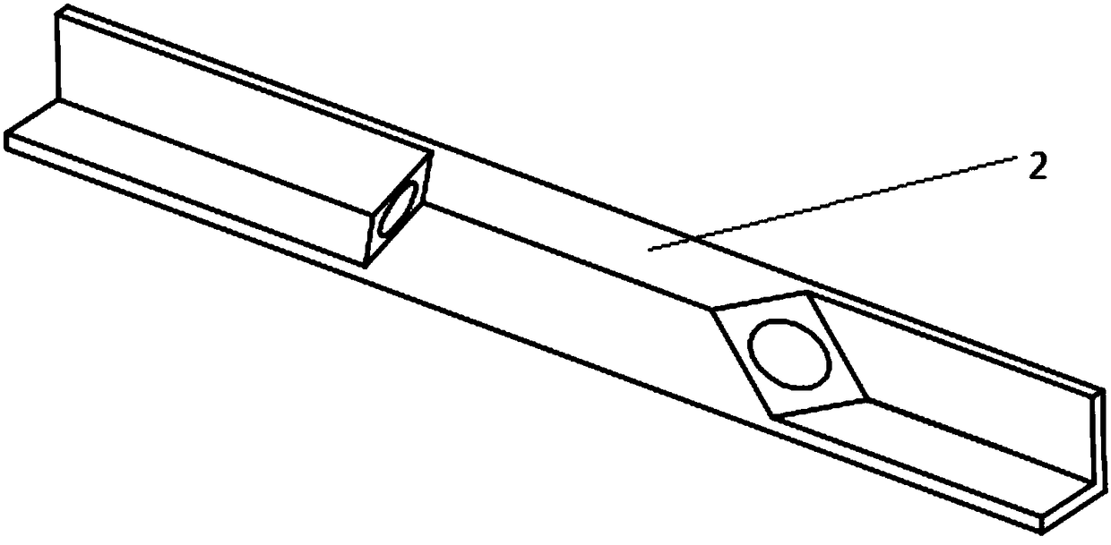
[0025] refer to Figure 1-Figure 6. In the embodiment described below, a two-degree-of-freedom low thermal resistance locking device consists of a one-way wedge surface fixing block 1, a one-way wedge surface fixing block 2, a double wedge surface block middle angle plate moving section 3, and a one-way wedge surface Angle plate moving section 4, one-way wedge surface driving sliding block 5 and screw rod 6 constitute. The one-way wedge surface fixing block 1 is fixed on the L-shaped notch groove 8 of the LRM module 9 by the locking screw 7 passing through the lateral screw hole a of the one-way wedge surface fixing block 1 of the side plate hole of the LRM module 9 . The one-way wedge fixed block 1 passes through the screw hole, and is coupled and connected to the corner section of the rear wedge block angle plate moving section 2 by a long screw rod. Similarly, one end of the wedge blo...


PUM


Abstract

The invention brings forward a double motion freedom degree low thermal resistance locking device. Via the device, contact thermal resistance can be remarkably reduced, vibration amplitude of an LRM module can be lowered, and vibration resistance performance of the module can be improved. The device is realized via the following technical solution: a one-way wedge face fixing block (1) fixed on anangle plate, a rear wedge face block angle plate moving section (2), a double wedge face block middle angle plate moving section (3), a one-way wedge face front angle plate moving section (4), and aone-way wedge face driving slide block (5) are orderly connected in series at an interval of 3-5 millimeters via long screw rods so as to form a cuboid-shaped locking bar comprising four moving pairsconnected in series, the locking bar is mounted fixedly in L-shaped gap slot of the LRM module, all angle plate moving sections are driven spirally via screw rods (6) to gradually retract along interval gaps among all sections, staggered sliding motion is generated along a direction of a diagonal line of a cuboid, distensible force is generated between walls of gap slots of the LRM module and a cold plate (10), and double motion locking and heat transfer of the LRM module can be realized.

Description

technical field [0001] The invention relates to a low thermal resistance locking device mainly used for LRM modules with dual motion degrees of freedom, especially for a replaceable module (Line Replacement module LRM) in avionics equipment. Background technique [0002] With the development of information technology, electronic equipment and its functions are becoming more and more complex and diverse. Such as avionics equipment, communication electronic equipment, etc., need to work with high reliability in harsh environments, and also require easy maintenance and repair. Therefore, these electronic devices often adopt a modular design scheme. In the modular design scheme, the electronic equipment is composed of several replaceable modules (Line Replacement module LRM). These modules are installed in the chassis in sequence, and the electrical signals between the modules are realized through the common backplane located in the chassis. On the one hand, there needs to be ...

Claims


Application Information

Patent Timeline
Patent Type & Authority Applications(China)
IPC IPC(8): H05K7/14H05K7/20
CPCH05K7/1401H05K7/20445
Inventor 胡家渝李俞先任建峰
Owner 10TH RES INST OF CETC
Why Eureka
Try Eureka