

Additive manufacturing machine including powder distribution system with tray and syringe
An additive manufacturing, injector technology, applied in machining, manufacturing tools, additive manufacturing, etc., can solve problems such as limiting the possibility of powder management, and achieve the effect of shortening manufacturing time and optimizing movement
- Summary
- Abstract
- Description
- Claims
- Application Information
AI Technical Summary
Problems solved by technology
Method used
Image

Examples
Embodiment Construction
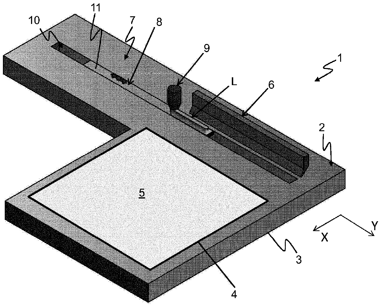
[0046] figure 1 The interior of a machine 1 for the additive manufacturing of components starting from powder material by complete or partial selective melting is shown schematically in detail. The material used can be, for example, metal or plastic. More specifically, figure 1 The working plane 2 inside the machine 1 corresponding to the cavity bottom is shown in . Preferably, the atmosphere within the chamber is inert with respect to the materials used.
[0047] For purposes of clarity and brevity, the working plane 2 is considered here to be horizontal. A longitudinal horizontal axis X and a transverse horizontal axis Y are then defined, parallel to the working surface 2 and orthogonal to each other. The adjective "longitudinal" and its alternatives hereinafter mean any direction parallel to the longitudinal axis X; likewise the adjective "transverse" and its alternatives hereinafter mean any direction parallel to the transverse axis Y.
[0048] More specifically, the ...
PUM
 Abstract
Description
Claims
Application Information