Flexible compound forming device and method based on magnetic pulse synchronous discharge

A discharge device and synchronous discharge technology, applied in the field of advanced manufacturing and forming, can solve the problems of poor mold flexibility, long forming cycle, low processing efficiency, etc., and achieve the effects of reducing production costs, suppressing material rebound, and improving forming quality.

Active Publication Date: 2018-08-24
HUAZHONG UNIV OF SCI & TECH
View PDF5 Cites 2 Cited by
  • Summary
  • Abstract
  • Description
  • Claims
  • Application Information

AI Technical Summary

Problems solved by technology

[0003] In the traditional electromagnetic forming technology, single-turn or multi-turn coil forming is usually used, and the electromagnetic discharge device is fixed and single, which has the following problems:
[0004] 1. Poor versatility
For different metal plates, the size of the coil structure is inconvenient to change
[0005] 2. Long molding cycle
In the process of processing, the electromagnetic discharge device needs to be processed step by step around the mold, and the processing efficiency is low
[0006] 3. When processing large metal plate parts, the coil structure is too large to cause material waste, which is not suitable for adjustment, while the coil is too small and the forming cycle will be too long
[0007] 4. Poor mold flexibility
The mold usually used in electromagnetic forming is a set of fixed integral non-detachable molds, the structure size is not easy to change, and it is difficult to meet the market demand for different molds in a short cycle

Method used


Image

  • Flexible compound forming device and method based on magnetic pulse synchronous discharge
  • Flexible compound forming device and method based on magnetic pulse synchronous discharge
  • Flexible compound forming device and method based on magnetic pulse synchronous discharge

Examples


Embodiment 1

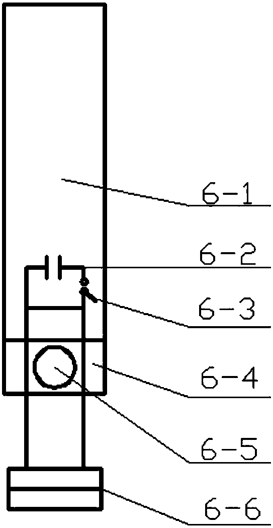
[0049] Such as figure 1 As shown, it is a magnetic pulse discharge device, which includes a coil fixing rod 6-1, a capacitor 6-2, a forming coil switch 6-3, a coil clamping plate 6-4, a bolt 6-5, and a forming coil 6-6;

[0050] The capacitor 6-2 is connected in series with the forming coil switch 6-3 and the forming coil 6-6 to form a loop; the capacitor 6-2 provides energy for the forming coil 6-6, and the forming coil switch is used to separately control the forming in the magnetic pulse discharge device 6 The coil 6-6 current switch; the coil clamping plate 6-4 is connected to the coil fixing rod 6-1; the height of the coil fixing rod 6-1 can be adjusted through the computer control system; the lines at the two ends of the forming coil 6-6 pass through the insulation It is connected with the coil clamping plate 6-4 with the bolt 6-5, and the lines at the two ends of the forming coil 6-6 are rotatable around the bolt 6-5.

[0051] The working process is to adjust the coil ...

Embodiment 2

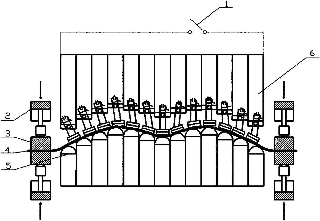
[0053] A flexible composite forming device based on magnetic pulse synchronous discharge is provided, based on the magnetic pulse discharge device in the foregoing embodiments, such as figure 2 As shown, it is a one-time molding surface forming diagram of the flexible composite forming device based on magnetic pulse synchronous discharge; the flexible composite forming device based on magnetic pulse synchronous discharge includes the main switch 1 of the discharge group, the hydraulic cylinder 2, the blank holder 3, the to-be-formed Plate 4, flexible multi-point mold 5, magnetic pulse discharge device 6;

[0054] A plurality of magnetic pulse discharge devices 6 are connected in parallel to each other to form a parallel circuit, the discharge group main switch 1 is connected in series with the parallel circuit, and the unified control circuit is switched on and off; The capacitor provides electric energy; the flexible multi-point mold 5 is composed of a plurality of discrete ...

Embodiment 3

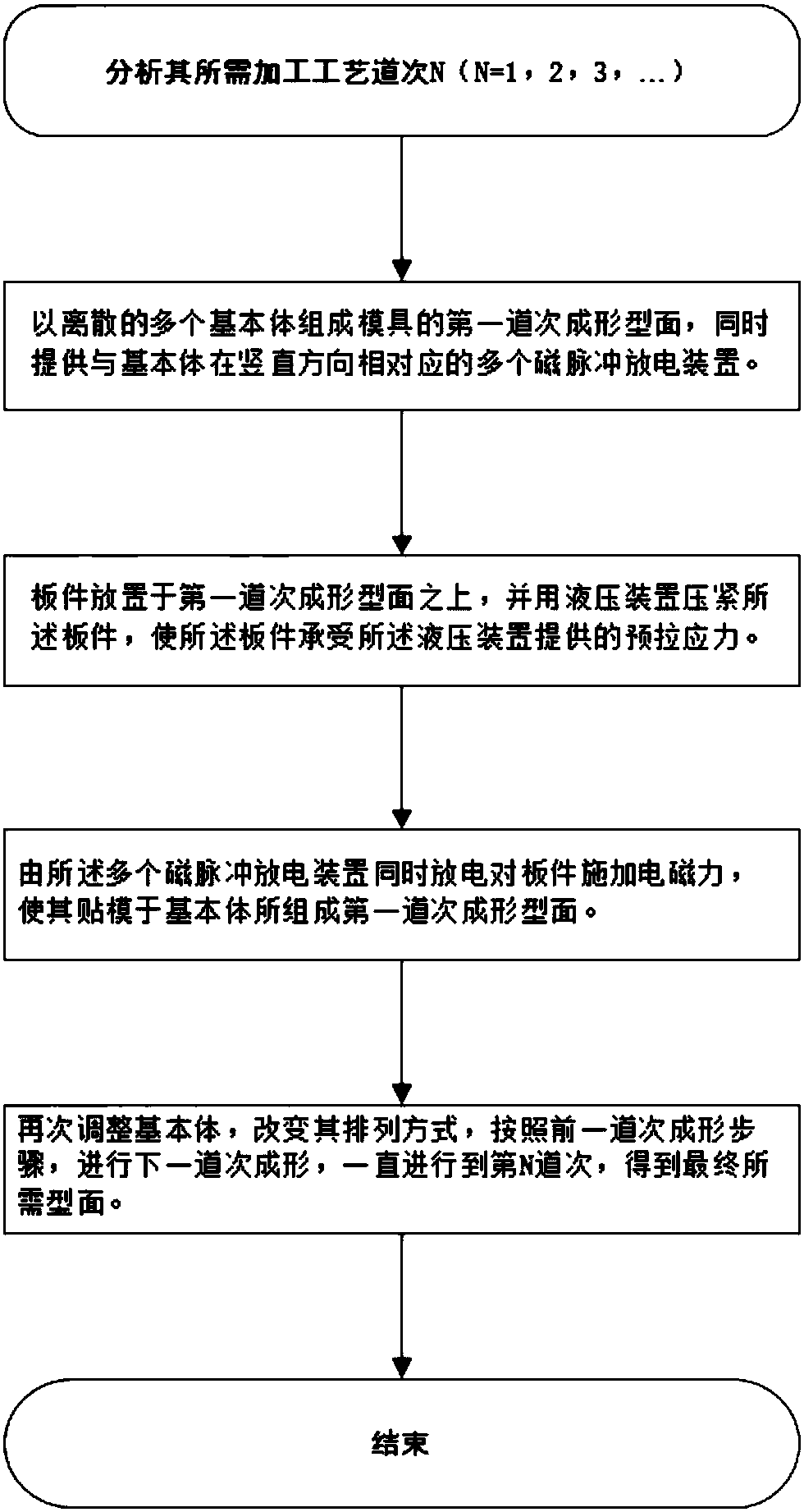
[0059] This embodiment provides a flexible composite forming method based on the flexible composite forming device of the foregoing embodiments. The main components and parameters involved in the method are set as follows:

[0060] The plate to be formed is an aluminum alloy plate, and the diameter of the area to be formed is 1000mm-1500mm; the maximum movable stroke of the coil fixing rod in the magnetic pulse discharge device is 400mm, and the diameter of the forming coil is 50mm; the flexible multi-point mold 5 The diameter of the ball head at the top of a plurality of discrete basic bodies is 60 mm; the number of hydraulic cylinders in the hydraulic device is 8-12; the flexible composite forming device based on magnetic pulse synchronous discharge in Embodiment 2 is used.

[0061] The material of the plate to be formed in the present invention is not limited to aluminum alloy, and the material can also be light-weight high-strength materials such as magnesium alloy and tita...


PUM


Abstract

The invention discloses a flexible compound forming device and method based on magnetic pulse synchronous discharge, and belongs to the technical field of advanced manufacturing forming. The flexiblecompound forming device comprises a discharge group main switch, a plurality of magnetic pulse discharge devices, a power source and a mold. The multiple magnetic pulse discharge devices are connectedwith each other in parallel to form a parallel circuit, and the parallel circuit is connected in series with the discharge group main switch and the power source. The discharge group main switch is used for uniformly controlling a current switch of a series circuit, and the power source is used for providing electrical energy for capacitors in the magnetic pulse discharge devices. The mold is used for forming a forming profile and being matched with the magnetic pulse discharge devices to complete forming of sheet materials. According to the flexible compound forming device and method based on the magnetic pulse synchronous discharge, by flexibly arranging the multiple magnetic pulse discharge devices, a flexible multi-point mold is combined, complex profile forming can be adapted, the forming efficiency and quality are improved, and the production cost is reduced.

Description

technical field [0001] The invention belongs to the technical field of advanced manufacturing and forming, and more specifically relates to a flexible composite forming device and method based on magnetic pulse synchronous discharge. Background technique [0002] The current plastic forming technology pursues high efficiency, high quality, low consumption and low cost, and requires a short product development cycle. Electromagnetic forming technology is a relatively advanced manufacturing technology at present. It originated in the 1950s. It has the advantages of high forming efficiency and can effectively reduce the springback of materials. It just meets this development demand. In metal plastic processing applications are gradually increasing. [0003] In the traditional electromagnetic forming technology, single-turn or multi-turn coil forming is usually used, and the electromagnetic discharge device is fixed and single, which has the following problems: [0004] 1. Poo...

Claims


Application Information

Patent Timeline
Patent Type & Authority Applications(China)
IPC IPC(8): B21D26/14
CPCB21D26/14
Inventor 冯飞袁鹏李建军黄亮苏红亮赵明杰肖望刘翔
Owner HUAZHONG UNIV OF SCI & TECH
Why Eureka
Try Eureka