Soldering and desoldering method and device of PCB component

A device and preheating device technology, applied in electric heating devices, auxiliary devices, welding equipment, etc., can solve the problems of short circuit of solder joints, thermal damage of components, low success rate and efficiency of welding and desoldering, and reduce the impact, The effect of improving efficiency and success rate

Inactive Publication Date: 2018-08-24
深圳市微组半导体科技有限公司 +1
View PDF5 Cites 2 Cited by
  • Summary
  • Abstract
  • Description
  • Claims
  • Application Information

AI Technical Summary

Problems solved by technology

[0005] However, the disadvantage of this method of soldering and desoldering is that when the heating is excessive or uneven, it is easy to cause a short circuit between adjacent solder j

Method used


Image

  • Soldering and desoldering method and device of PCB component
  • Soldering and desoldering method and device of PCB component
  • Soldering and desoldering method and device of PCB component

Examples


Embodiment Construction

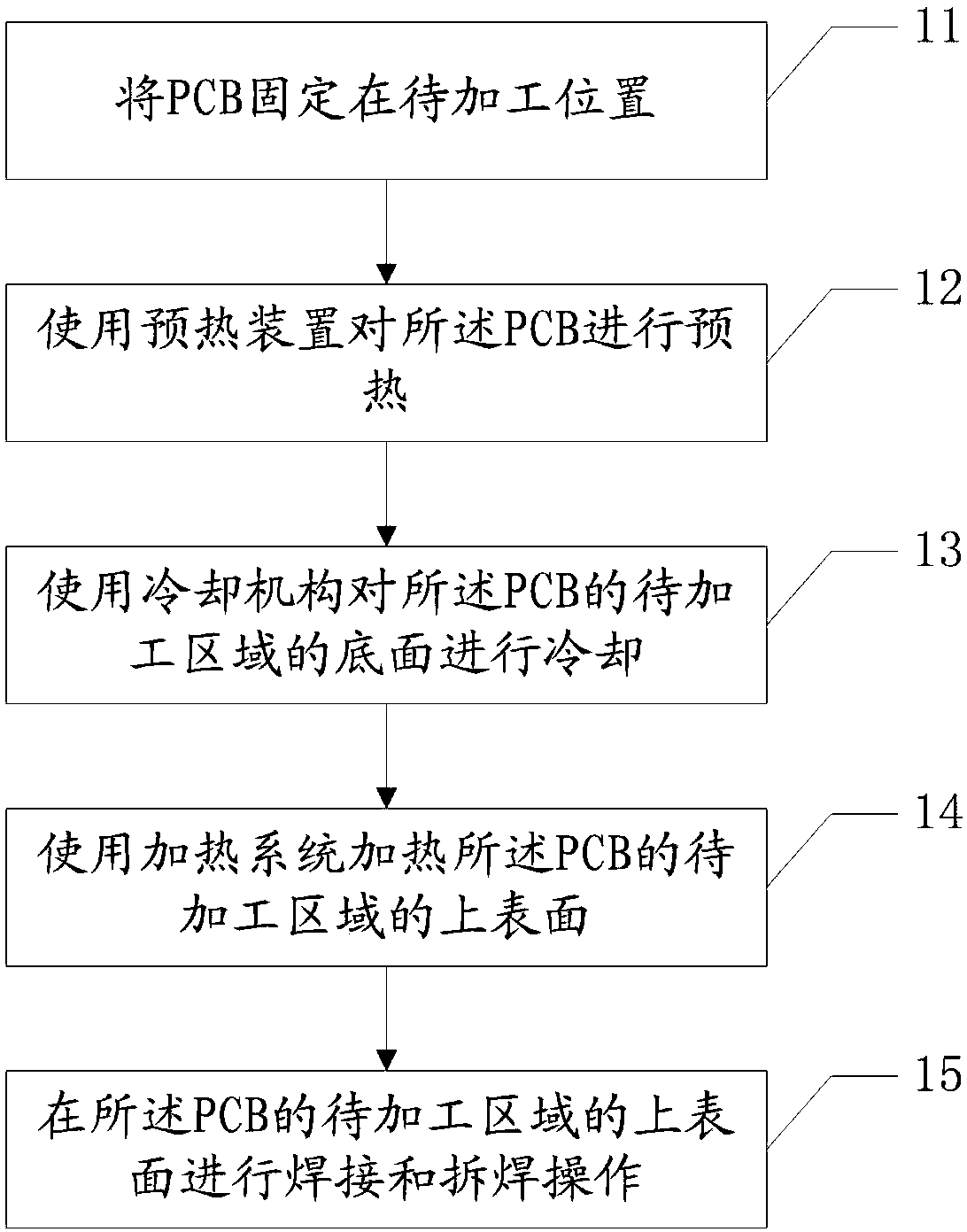
[0034] Embodiments of the present invention provide a PCB device soldering and desoldering method and device, which are used to provide temperature difference environmental conditions for PCB soldering and desoldering, thereby improving the efficiency and success rate of PCB soldering and desoldering.

[0035] In order to enable those skilled in the art to better understand the solutions of the present invention, the following will clearly and completely describe the technical solutions in the embodiments of the present invention in conjunction with the drawings in the embodiments of the present invention. Obviously, the described embodiments are only It is an embodiment of a part of the present invention, but not all embodiments. Based on the embodiments of the present invention, all other embodiments obtained by persons of ordinary skill in the art without making creative efforts shall fall within the protection scope of the present invention.

[0036] The terms "first", "se...


PUM


Abstract

The embodiment of the invention discloses a soldering and desoldering method and device of PCB component, and aims at supplying a temperature difference environment condition for PCB soldering and desoldering in order to improve the PCB soldering and desoldering efficiency and success rate. The method in the embodiment comprises the steps of fixing the PCB to a position for processing; preheatingthe PCB through a preheating device; cooling the bottom surface of an area, to be processed, of the PCB through a cooling mechanism; heating the upper surface of the area, to be processed, of the PCBthrough a heating system; and performing soldering and desoldering operation on the upper surface of the area, to be processed, of the PCB. According to the method, the PCB is stably preheated throughthe preheating device; the area, to be processed, of the PCB is cooled through the cooling mechanism; and then the upper surface of the area, to be processed, of the PCB is heated through the heatingsystem, thus the soldering and desoldering temperature difference is realized, and the influence on components surrounding soldering and desoldering elements and components can be decreased, and as aresult, the PCB soldering and desoldering efficiency and success rate can be improved.

Description

technical field [0001] The invention relates to the technical field of PCB technology, in particular to a PCB device soldering and desoldering method and device. Background technique [0002] With the continuous development of related electronic technology fields, the corresponding electronic technology has been widely used. In order to meet the requirements of smaller electronic products, electronic product manufacturing has increasingly adopted precision assembly of micro-components. [0003] In this context, the common feature of printed circuit board (PCB, Printed Circuit Board) manufacturers such as smartphones, solid-state drives, and servers is that they are basically limited by space. Under the condition of high performance, the common practice in the industry is The components are soldered on both sides of the PCB board, which leads to more and more types and quantities of components used on the circuit board. In the soldering process of PCB components, it is easy ...

Claims


Application Information

Patent Timeline
IPC IPC(8): B23K1/005B23K1/018B23K3/04B23K3/08B23K101/42
CPCB23K1/0056B23K1/018B23K3/04B23K3/085
Inventor 林佛迎胡梅发
Owner 深圳市微组半导体科技有限公司
Why Eureka
Try Eureka