Device and method for preheating plastic extrusion molding die
A technology for extrusion molding and molding die, which is applied to the device for preheating plastic extrusion molding die and the field of preheating plastic extrusion molding die, which can solve the problems of easy separation and peeling off coating, achieve stable preheating, improve efficiency, and improve The effect of stability
- Summary
- Abstract
- Description
- Claims
- Application Information
AI Technical Summary
Problems solved by technology
Method used
Image
Examples
Embodiment 1
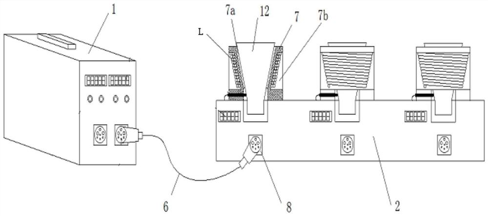
[0048] Such as figure 1 As shown, the embodiment of the present invention provides a rapid start-up preheating equipment for plastic extrusion molds, including a high-frequency generator 1, a preheating platform 2 and a communication cable 6; the preheating platform 2 includes a plurality of specification fixtures The sheath 7 , the single-chip microcomputer 8 and the induction coil L are helically wound and embedded in the fixture sheath 7 , and are connected to the high-frequency generator 1 through the communication cable 6 .
[0049] see figure 1 As shown, the clamp sheath 7 is provided with a funnel cavity 7a inside and a trapezoidal groove 7b outside, and the inlaid induction coil L is wound in the trapezoidal groove 7b.
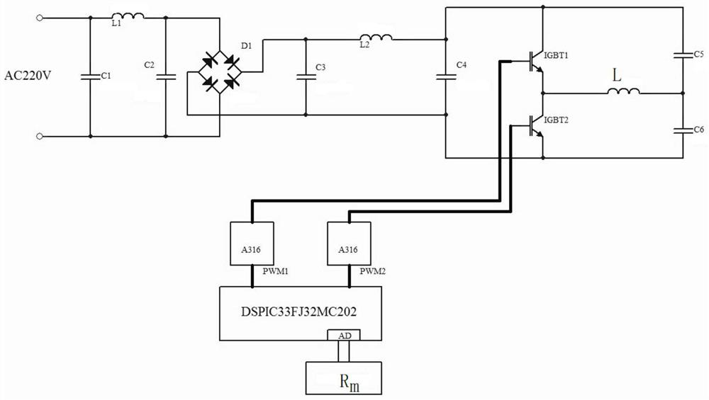
[0050] The high-frequency generator 1 is equipped with a power supply, and the power supply includes an AC input terminal AC220V, a filter voltage stabilization circuit, and a rectifier bridge. The AC input from the AC input terminal AC220V is filtere...
Embodiment 2
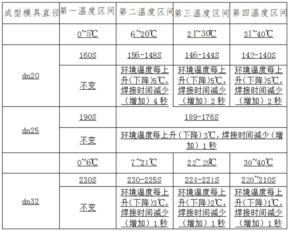
[0065] On the basis of Embodiment 1, the single-chip microcomputer 8 also measures the ambient temperature outside the funnel chamber 7a by the temperature sensor, as in Table 2, the single-chip microcomputer is based on the measured ambient temperature Th and the standard temperature T in different temperature ranges hi Calculate the compensation value s of the conduction time required by the forming mold with a diameter of dn32, and then update the conduction time t of the PWM1 and PWM2 signals by the microcontroller d , t d = t d +s, where the standard temperature T hi Including 6°C, 21°C, 29°C, 40°C;
[0066] The first temperature range is 0-6°C, s=0;
[0067] The second temperature range is from 7 to 21°C, and the compensation value s is increased by 1s for every 3°C increase in the ambient temperature;
[0068] The third temperature range is 22-29°C. For every 2°C increase in the ambient temperature, the compensation value s will be increased by 1s;
[0069] The fou...
Embodiment 3
[0078] includes the apparatus of Example 1, but with a fixed value resistor R m replaced by common resistors such as Figure 4 a and Figure 4 b, and the coil KT of the time relay is connected in series between the voltage dividing resistor R and the ground terminal GND or the reference DC power supply VCC, and the normally closed contact KT1 of the time relay is also connected in series between the AD converter and the voltage dividing resistor R or the ground terminal GND , identifying the resistor R m When it is connected between the voltage dividing resistor R or the ground terminal GND, the single-chip microcomputer collects and identifies the resistance R through the AD converter. m Divide the voltage Vr and store the AD value. After the delay of the coil KT of the relay arrives, the normally closed contact KT1 of the time relay is disconnected, and the resistance value measured by the single-chip microcomputer changes greatly, and the single-chip microcomputer is exci...
PUM
 Abstract
Description
Claims
Application Information
 - R&D
- Intellectual Property
- Life Sciences
- Materials
- Tech Scout
- Unparalleled Data Quality
- Higher Quality Content
- 60% Fewer Hallucinations
Browse by: Latest US Patents, China's latest patents, Technical Efficacy Thesaurus, Application Domain, Technology Topic, Popular Technical Reports.
© 2025 PatSnap. All rights reserved.Legal|Privacy policy|Modern Slavery Act Transparency Statement|Sitemap|About US| Contact US: help@patsnap.com


