

Floating plant radar detection system
A technology for radar detection and floating plants, which is applied in the field of radar detection systems for floating plants, and can solve the problems such as the shortage of fishing power.
- Summary
- Abstract
- Description
- Claims
- Application Information
AI Technical Summary
Problems solved by technology
Method used
Image


Examples
Embodiment Construction
[0103] The technical solution of the present invention is further described in detail below in conjunction with specific examples, but the protection scope of the present invention is not limited to the following description.
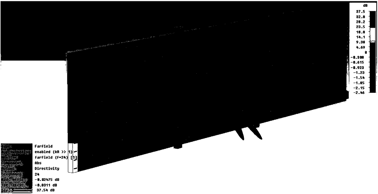
[0104] The aquatic plant detection radar adopts a narrow beam in azimuth to realize the minimum resolution unit of the measurement section; a wide beam is used in the elevation angle, and the energy covers the entire measurement section, and the echo intensity of each distance point in the section dimension is measured through a broadband signal. And the area of aquatic plants is determined by the change of echo intensity with or without aquatic plants.
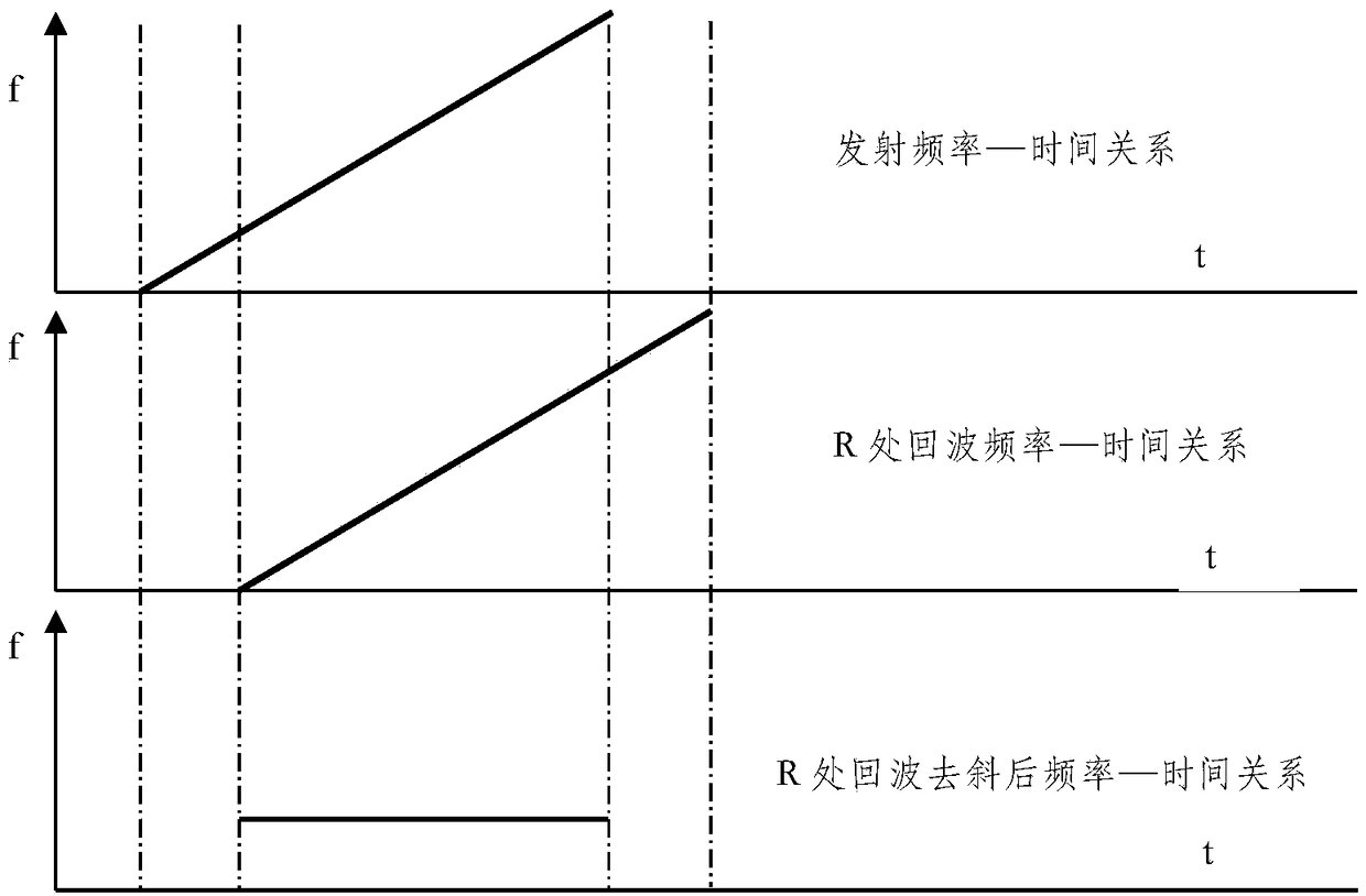
[0105] The radar generates point frequency continuous wave and linear frequency modulation continuous wave signals, of which the point frequency signal is only used for the speed measurement of floating objects on the water surface, and the linear frequency modulation continuous wave signal realizes t...
PUM
| Property | Measurement | Unit |
|---|---|---|
| Antenna gain | aaaaa | aaaaa |
| Center frequency | aaaaa | aaaaa |
| Power consumption | aaaaa | aaaaa |
Abstract
Description
Claims
Application Information