
Power distribution method for direct current microgrid composite energy storage system

A DC microgrid and composite energy storage technology, applied in the direction of load balancing, current collectors, electric vehicles, etc. in the DC network, can solve the problems of unbalanced distribution, affect the operation characteristics of energy storage devices, etc., and achieve the goal of improving the accuracy of power distribution. Effect

Active Publication Date: 2018-08-24
HUAZHONG UNIV OF SCI & TECH
View PDF6 Cites 10 Cited by
  • Summary
  • Abstract
  • Description
  • Claims
  • Application Information

AI Technical Summary

Problems solved by technology

However, the line resistance parameters in the DC microgrid have a significant impact on the distribution of unbalanced power, which will lead to unbalanced distribution of unbalanced power among the same type of energy storage, and affect the operating characteristics of the energy storage device.

Method used


Image

  • Power distribution method for direct current microgrid composite energy storage system
  • Power distribution method for direct current microgrid composite energy storage system
  • Power distribution method for direct current microgrid composite energy storage system

Examples


Embodiment Construction

[0035] In order to make the object, technical solution and advantages of the present invention clearer, the present invention will be further described in detail below in conjunction with the accompanying drawings and embodiments. It should be understood that the specific embodiments described here are only used to explain the present invention, not to limit the present invention. In addition, the technical features involved in the various embodiments of the present invention described below can be combined with each other as long as they do not constitute a conflict with each other.

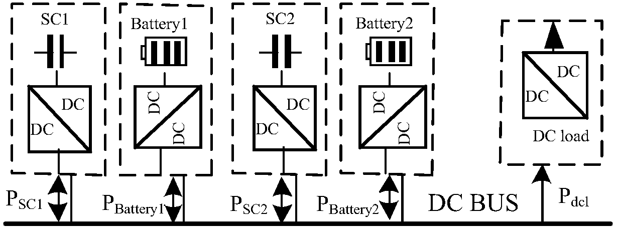
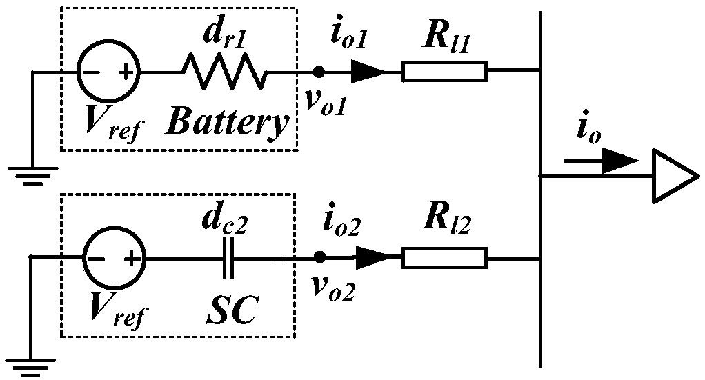
[0036] figure 1 Shown is a 400V low-voltage DC micro-grid system composed of two batteries and two supercapacitors. Each energy storage unit is connected to a DC / DC converter and then connected to the DC bus through the line impedance. figure 2 shown as figure 1 The equivalent circuit diagram of a storage battery and a supercapacitor in the shown system, the line impedance equivalent is a vir...


PUM


Abstract

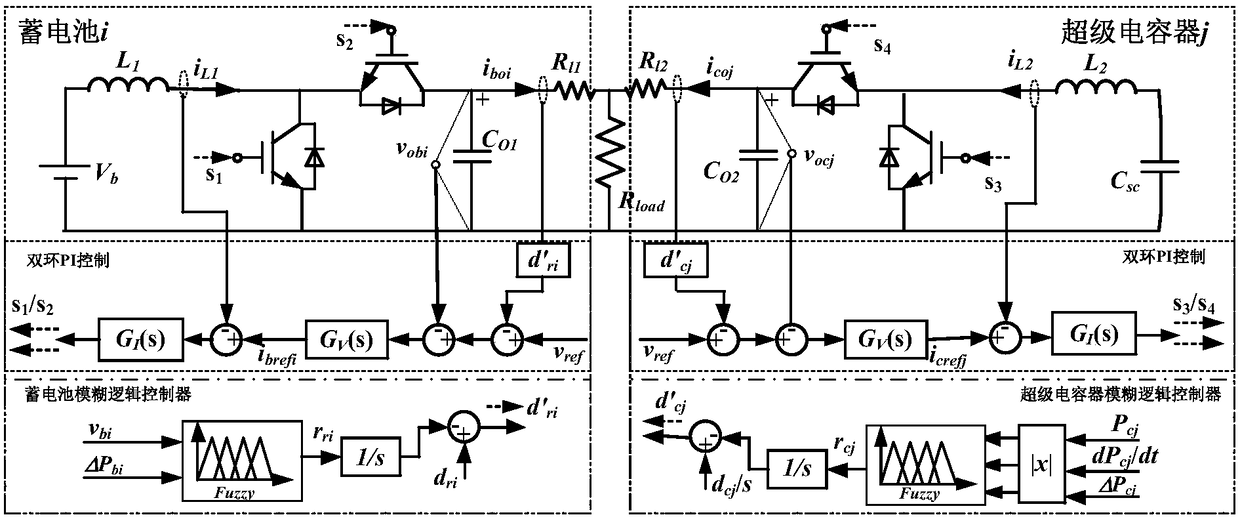
The invention discloses a power distribution method for a direct current microgrid composite energy storage system. The power distribution method comprises the following steps: calculating the resistive droop coefficient of each branched circuit of a storage battery; calculating the capacitive droop coefficient of each branched circuit of a supercapacitor bank; obtaining the output voltage and unbalanced power of a storage battery branched circuit converter, carrying out fuzzy logical processing on the two obtained parameters, and using an output signal for the fuzzy logical processing to adjust the resistive droop coefficient; obtaining the output power of a supercapacitor branched circuit, the power change rate and unbalanced power of the converter, carrying out fuzzy logical processingon the absolute values of the three obtained parameters, and using an output signal for the fuzzy logical processing to adjust the capacitive droop coefficient; and carrying out resistive and capacitive droop control on a direct current microgrid according to the resistive droop coefficient and the capacitive droop coefficient after adjusted. According to the method, the unbalanced power among different energy storage according to frequency distribution is realized, the distribution accuracy is improved, the response speed of supercapacitors is increased, and the supercapacitors are of good expandability.

Description

technical field [0001] The invention belongs to the technical field of electrical engineering, and more specifically relates to a power distribution method for a DC microgrid composite energy storage system. Background technique [0002] With the development of power electronics technology and the growth of new energy generation, microgrids that integrate distributed power sources, loads, and energy storage devices have received extensive attention. Microgrids can be divided into AC microgrids and DC microgrids in terms of types. Compared with the AC microgrid, the DC microgrid has no problems such as frequency stability and reactive power loss. At the same time, the control is relatively simple and the construction cost is relatively low. It will become a trend in the future development of microgrids. In a DC microgrid, the output of renewable energy such as wind power and photovoltaics is random and volatile, which will lead to system power imbalance, affect the stability...

Claims


Application Information

Patent Timeline
IPC IPC(8): H02J1/14H02J7/34
CPCH02J1/14H02J7/345
Inventor 陈霞闫林芳石梦璇周建宇文劲宇
Owner HUAZHONG UNIV OF SCI & TECH
Learn More