Dewatering device for inner chamber of hose and operation method thereof

A dehydration device and hose technology, applied in the direction of drying solid materials, centrifuges, and drying solid materials without heating, can solve the problems of precision and complexity, long time and low efficiency of infusion sets, and achieve convenient use, low cost, high efficiency effect

Pending Publication Date: 2018-08-28
刘一成
View PDF0 Cites 5 Cited by
  • Summary
  • Abstract
  • Description
  • Claims
  • Application Information

AI Technical Summary

Problems solved by technology

The shape of the vitrified head tube is similar to that of an intravenous infusion set, but it is far more sophisticated than an infusion set
The glass cutting head is divided into 20G / 23G / 25G / 27G and other specifications according to the diameter. Taking 25G as an example, the outer diameter is 0.5mm and the inner diameter is less than 0.4mm. After use, human tissue and protein will remain in the tube. It cannot be cleaned after use, it can only be used as a disposable consumable and cannot be reused
If you put it directly into the drying cabinet after washing, even if you use negative pressure to dry, because the pipeline is long and the opening is small, there will still be water droplets in the tube after drying for several days, and the time is too long to accept
The glass cutting head tube is not heat-resistant and cannot be baked. The pipeline is too long to unfold it all at once and shake the water by hand. Ordinary centrifuges cannot dehydrate it. At present, it can only be blown off manually with air, which is inefficient, expensive and easy. Secondary pollution to the cleaned vitrified head tube leads to medical accidents
When using negative pressure to suck out the moisture in the inner cavity, the bacterial dust in the air will be enriched on the inner wall of the wet pipeline; when blowing out with compressed air, the oil and impurity particles brought out by the compressed air will also adhere to the inner wall of the pipeline, so At present, there is no ideal method for dehydrating ultra-long hose medical devices that require cleanliness on both sides of the inner and outer walls of the pipeline

Method used


Image

  • Dewatering device for inner chamber of hose and operation method thereof
  • Dewatering device for inner chamber of hose and operation method thereof
  • Dewatering device for inner chamber of hose and operation method thereof

Examples


Embodiment Construction

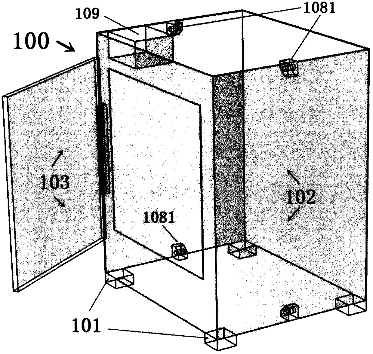
[0088] The object of the present invention is to provide a hose lumen dehydration device to solve the above problems. It is especially suitable for super-long hoses with impermeable outer walls (such as vitrectomy head tubes, tourniquets, silicone suction tubes, urinary catheters) or medical devices with small openings and large cavities (such as ear washing balls, guide needle guards, etc.) sets, respirators, nebulizers) for dehydration. Using the device of the invention instead of manpower manual operation can significantly improve labor productivity and avoid secondary pollution caused by compressed air or negative pressure suction. Especially when the lumen-shaped instruments are processed in batches with the decompression boiling washing machine, the coiled hose is taken out from the washing machine and directly put into the device of the present invention for dehydration without unfolding. The operation is extremely simple and the effect is excellent and obvious. The ho...


PUM


Abstract

The invention discloses a dewatering device for an inner chamber of a hose. The device comprises a centrifugal device, a rotor device and a power system, wherein the centrifugal device comprises a centrifugal shaft which is connected to the power system, and a centrifugal rack which is connected to the centrifugal shaft; the rotor device comprises a rotor which is connected to the power system, and a rotor shaft which is fixedly connected to the centrifugal shaft through the centrifugal rack; axes of the rotor shaft and the centrifugal shaft are parallel to each other and are distributed at acertain interval. According to the dewatering device, the rotor loaded with a material is driven by the power system to revolute to produce centrifugal force and synchronously revolve on own axis to change the direction of the centrifugal force, thus water in the empty chamber of the material continuously changes the position to seek for an open end port in order to be drained, and thus the dewatering of the inner chamber of the hose is achieved. The invention also provides a dewatering operating method of the inner chamber of the hose. The method comprises the steps of classifying the hose; fixing the hose into the rotor through a clamping device; and starting the abovementioned device to drive the rotor to move. The device and the method are low in cost, high in efficiency, and convenient to use.

Description

【Technical field】 [0001] The invention relates to the technical field of medical devices, and relates to a dehydration device for the inner cavity of a hose and a dehydration method thereof. 【technical background】 [0002] A centrifugal dehydrator is a mechanical device that uses centrifugal force to separate solids and liquids. The material to be dehydrated in the centrifuge is attached to the wall of the barrel with small holes by the centrifugal force in the high-speed rotating centrifugal barrel (also known as the rotating inner tank or drum), and the liquid in the material can penetrate the small holes and splash The filtrate is collected on the inner wall of the outer barrel, and the solid is left in the centrifuge barrel and collected manually to achieve material dehydration or solid-liquid separation. [0003] Centrifugal dehydration is currently the most efficient means of solid-liquid separation, widely used in metallurgy, chemical industry and other occasions. H...

Claims


Application Information

Patent Timeline
Patent Type & Authority Applications(China)
IPC IPC(8): B04B5/02F26B5/08
CPCB04B5/02F26B5/08
Inventor 刘一成
Owner 刘一成
Why Eureka
Try Eureka