Anti-corrosive construction process for inner surface of oil tank in service based on laser technology

A technology of laser technology and construction technology, which is applied in the field of anti-corrosion construction technology on the inner surface of oil tanks in service, can solve the problems of not meeting the roughness of the inner lining layer, easy to pollute the environment, and narrow space in the tank, and achieve the best market promotion and The effect of low requirements on application and site conditions and high construction efficiency

Active Publication Date: 2018-08-28
重庆搏成防腐工程有限公司
View PDF2 Cites 2 Cited by
  • Summary
  • Abstract
  • Description
  • Claims
  • Application Information

AI Technical Summary

Problems solved by technology

[0005] 1. Occupational injuries are serious, and workers who work for a long time are prone to occupational diseases such as pneumoconiosis;
[0006] 2. The problem of environmental protection is serious and it is easy to pollute the environment;
[0007] 3. The space inside the tank is narrow, the construction noise is huge, and it is easy to damage the hearing of the operator;
[0008] 4. The site requirements are high, and a special site is required for sand placement and sand screening;
[0009] 5. The processing accuracy is difficult to control, and it is easy to cause damage to the local devices attached to the rusted part;
[0010] 6. The construction of the inner lining layer cannot be followed up in time, because after the sandblasting treatment is completed, the dust inside the tank body is serious, and the inner lining layer construction can only be carried out after waiting;
[0011] 7. Waste sand treatment will cause secondary pollution, and the cost of waste sand transfer is high
However, although the current laser cleaning method can clean the surface of the steel structure, the surface of the finished steel structure does not have the roughness that meets the adhesion of the inner lining layer, and cannot meet the requirements of anti-corrosion construction at all.

Method used


Image

  • Anti-corrosive construction process for inner surface of oil tank in service based on laser technology
  • Anti-corrosive construction process for inner surface of oil tank in service based on laser technology
  • Anti-corrosive construction process for inner surface of oil tank in service based on laser technology

Examples


Embodiment approach

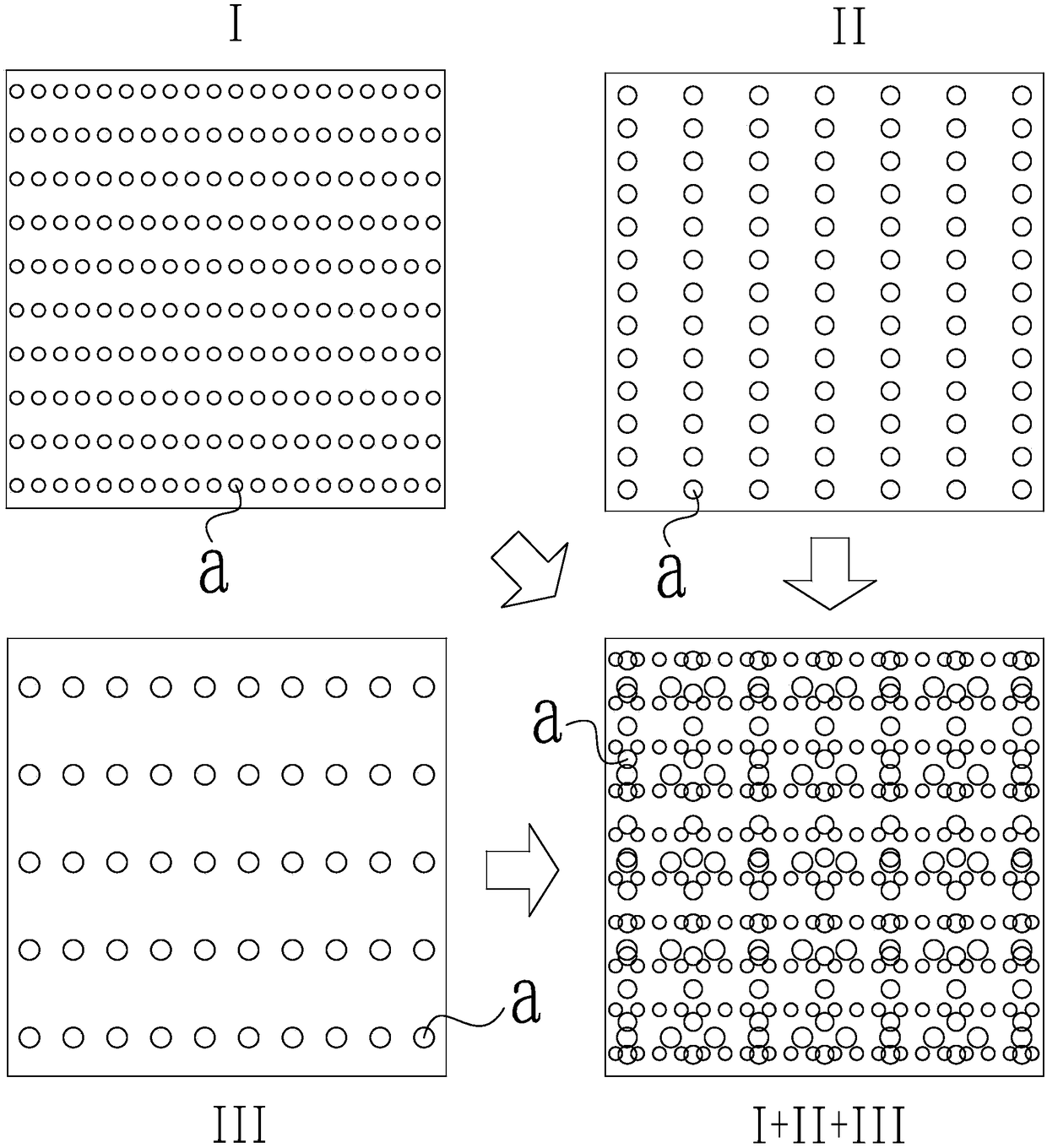
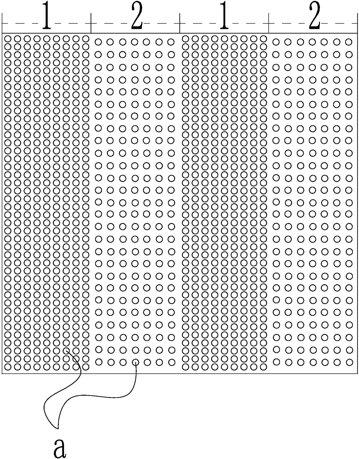
[0070] See figure 2 , the micro-surface structure is composed of pits a arranged in disorder, forming a disordered rough surface on the inner surface of the tank, so as to greatly improve the adhesion of the inner lining. Specifically, the micro-surface structure is obtained by scanning the inner surface of the tank at least twice by the laser generating equipment, and the path of any laser scanning is perpendicular to the path of the previous laser scanning, that is, horizontal and vertical alternate construction. Further, and the density of the pits a formed by any laser scanning is less than the density of the pits a formed by the previous laser scanning, the size of the pits a formed by any laser scanning is greater than the pits formed by the previous laser scanning the size of a. The inner surface of the tank is rapidly formed with pits a of different sizes and arranged in disorder, so that the roughness of the inner surface of the tank reaches the anti-corrosion stand...


PUM


Abstract

The invention discloses an anti-corrosive construction process for the inner surface of an oil tank in service based on a laser technology. The process comprises the following steps: S1, acceptance check before anti-corrosive treatment; S2, in tank air detection; S3, surface laser treatment; S4, roughness measurement; S5, liner layer construction; S6, liner layer thickness detection; S7, static conducting layer coating; and S8, static conducting performance test. The anti-corrosive construction process for the inner surface of the oil tank in service based on the laser technology has the advantages of being high in construction efficiency, low in field condition demand, low in safety risk, good in economical benefit, free of environment influence and occupational injury, large in adhesiveforce of a liner layer, long in service life and the like, and has extremely excellent market proportion and application applications.

Description

technical field [0001] The invention belongs to the technical field of anticorrosion engineering, and in particular relates to an anticorrosion construction process for the inner surface of an in-service oil tank based on laser technology. Background technique [0002] In the past, domestic gas stations mostly used steel single-layer horizontal buried oil tanks. The leakage of these oil tanks has not been paid enough attention, and there is also a lack of systematic investigations. Fuel oil leakage often pollutes groundwater sources. With the gradual enhancement of public awareness of environmental protection, the safety and environmental protection issues of gas stations have become increasingly prominent, especially the environmental risks caused by the leakage of underground oil tank systems in gas stations, which have become the focus of attention from all walks of life. [0003] In view of the fact that there are still a large number of buried steel single-layer horizon...

Claims


Application Information

Patent Timeline
Patent Type & Authority Applications(China)
IPC IPC(8): B05D7/14B05D7/00B08B7/00B08B9/08
CPCB05D7/14B05D7/54B08B7/0042B08B9/08
Inventor 刘川李晓春胡贵春龚佳红田方
Owner 重庆搏成防腐工程有限公司
Why Eureka
Try Eureka