Winding and coating device for anti-corrosion composite belt of elbow pipe winding machine

A technology of coating device and composite tape, which is applied in the direction of pipeline anti-corrosion/rust protection, damage protection, pipeline protection, etc., can solve the problem that the heating temperature of polyethylene composite tape cannot be reached, the tension control of polyethylene composite tape is uneven, and the reduction of polymerization Solve problems such as the winding quality of vinyl composite tapes, and achieve the effects of improving the quality of winding wrapping, improving the uniformity of tension control, and enhancing the bonding performance

Pending Publication Date: 2018-08-28
LUOYANG INST OF SCI & TECH
0 Cites 4 Cited by

AI-Extracted Technical Summary

Problems solved by technology

[0004] In order to solve the above-mentioned technical problems, the present invention provides a wrapping and wrapping device for the anticorrosion composite tape of the bend pipe winding machine. The control of the anti-corrosion composite tape is precise; the invention can solve the problem that the heating temperature of the polyethylene composite tape cannot be reached by using a hot air blower during the winding process of the anti-corrosion composite tape, which affects the adhesion of the polye...

Method used

The use process of the wrapping coating device of the anticorrosion composite belt of this bending pipe winding machine is: drive the driven wheel 3 to drive the rotary disk 1 to rotate at the driving device, and the polyethylene composite belt is continuously output from the belt feed wheel 2 at the same time. The pressure rod 516 in the tension control device 5 passes through the heating shell 401 of the heating device 4 at the same time, and the polyethylene composite tape 8 is heated in advance by the heating device 4; the heated polyethylene composite tape 8 is continuously wound and coated on the elbow 7 on; open the speed regulating motor 508 now, drive the friction wheel 504 to rotate by the speed regulating motor 508, the roller groove that forms between the front friction roller 505 in the friction wheel 504 and the rear friction roller 506, the same annular boss 502, limit The inner surface of the bit boss 503 and the wheel hub 501 forms a step contact surface with a high front end and a low rear end on the inner ring of the wheel 501, and they are in close contact; when the rotary disk 1 is constantly rotating, the polyethylene composite belt 8 is coiled on the...

Abstract

The invention discloses a winding and coating device for an anti-corrosion composite belt of an elbow pipe winding machine. A heating device is fixedly arranged on a revolving disc and is positioned at the bottom of a belt feeding wheel arranged on the back part of the revolving disc; a tension controlling device is fixedly arranged on the upper part of the heating device and is fixedly connectedwith the left end of the belt feeding wheel; a hammering device is fixedly arranged at the front end position of the revolving disc and is fixedly connected with a left wall of the revolving disc; anelbow pipe penetrates through the center of the revolving disc; a polyethylene composite belt penetrates through the belt feeding wheel and the tension controlling device, and also penetrates throughthe heating device and is wound and coated on the elbow pipe at the same time. According to the winding and coating device for the anti-corrosion composite belt of the elbow pipe winding machine disclosed by the invention, the winding and coating quality of the elbow pipe are greatly improved, the uniformity of the tension control of the polyethylene composite belt is improved, the pressure resistance and abrasion resistance performance of the elbow pipe are enhanced, a heating temperature of the polyethylene composite belt is increased, and the adhesion performance of the polyethylene composite belt is enhanced.

Application Domain

Technology Topic

Image

  • Winding and coating device for anti-corrosion composite belt of elbow pipe winding machine
  • Winding and coating device for anti-corrosion composite belt of elbow pipe winding machine
  • Winding and coating device for anti-corrosion composite belt of elbow pipe winding machine

Examples

  • Experimental program(1)

Example Embodiment

[0028] The specific embodiments of the present invention will be further described in detail below with reference to the accompanying drawings.
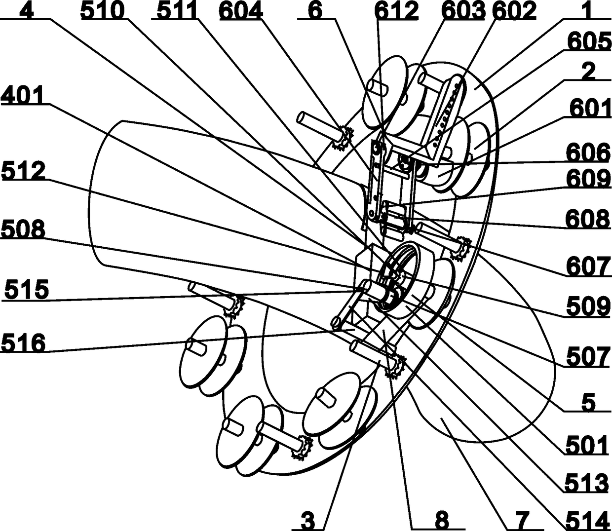
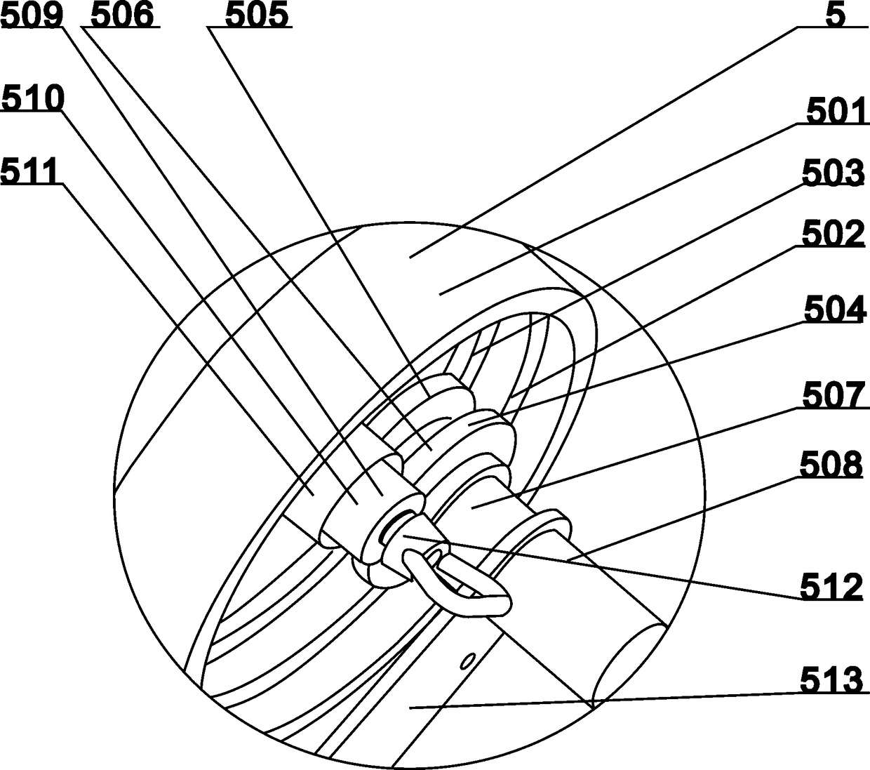
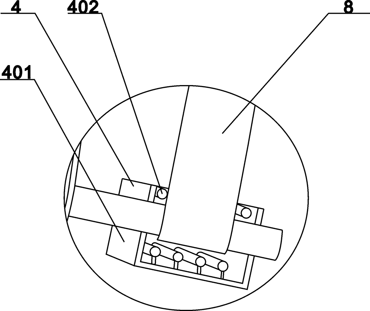
[0029] As shown in the figure, a winding and coating device for anti-corrosion composite tape of a elbow winding machine includes a rotary disc 1, a belt feeding wheel 2, a driven wheel 3, and a heating device 4; The round hole of the belt feeding wheel 2 is fixedly arranged in the circumferential direction of the turntable 1, and is evenly arranged at equal intervals. The driven wheel 3 is fixedly arranged at the middle position of the belt feeding wheel 2; the heating device 4 is fixedly arranged on the turntable 1, The heating device 4 is located at the bottom of the belt feeding wheel 2 on the back of the turntable 1, the tension control device 5 is fixed on the upper part of the heating device 4, and the tension control device 5 is fixedly connected to the left end of the belt feeding wheel 2; the beating device 6 is fixed Set at the front end of the turntable 1, the beating device 6 is fixedly connected to the left wall of the turntable 1; the elbow 7 passes through the center of the turntable 1, and the polyethylene composite belt 8 is passed through the belt pulley 2 and the tension control device 5. At the same time, it passes through the heating device 4 and wraps it on the elbow 7.
[0030] The heating device 4 includes a heating shell 401. The heating shell 401 is a rectangular parallelepiped hollow. The heating tubes 402 are evenly spaced across the upper and lower portions of the heating shell 401, and are evenly fixed. The heating tubes located on the upper part of the heating shell 401 and The heating tube at the bottom is arranged in parallel and symmetrically up and down.
[0031] The tension control device 5 includes a hub 501, the hub 501 is fixedly arranged on the outside of the belt feeding wheel 2, an annular boss 502 is fixedly arranged in the middle of the inner ring of the hub 501, and a limit convex is fixedly arranged on the front side of the annular boss 502 The platform 503, the annular boss 502 and the limit boss 503 are fixedly connected to the inner ring surface of the hub 5. The height of the limit boss 503 is higher than the height of the ring boss 502; the rear end of the friction wheel 504 is fixedly provided with a connecting shaft 507, the rear end of the connecting shaft 507 is fixedly provided with a speed regulating motor 508, and the friction wheel 504 is in close contact with the annular boss 502 and the limit boss 503; the friction adjusting device 509 is fixed at the center position of the hub 5, and the friction is adjusted The device 509 includes a central shaft 510, the central shaft 510 is fixedly arranged at the center position of the hub 5, the outer part of the central shaft 510 is fixedly provided with a cylindrical shell 511, and the fixed handle 512 is fixedly arranged on the outer end of the central shaft 510 by means of bolts. The force adjusting device 509 is fixedly connected to the belt feeding wheel 2; the connecting plate 513 is fixedly arranged at the connection of the connecting shaft 7 and the speed regulating motor 508, and the connecting plate 513 and the toggle plate 514 are fixedly hinged by a pin 515; at the bottom end of the toggle plate 514 A pressing rod 516 is fixedly arranged, and the left end of the pressing rod 516 is fixedly connected with the toggle plate 514, and a gap is left between the right end of the pressing rod 516 and the rotary disk 1.
[0032] The friction wheel 504 includes a front friction roller 505, which is fixedly arranged on the front side of the inner ring of the hub 5. A rear friction roller 506 is arranged in parallel on the rear side of the front friction roller 505, the front friction roller 505 and the rear friction roller The roller groove formed between the rollers 506 is in close contact with the annular boss 502, the limiting boss 503, and the inner surface of the hub 5. The inner ring of the hub 5 forms a step contact surface with high front end and low rear end.
[0033] The beating device 6 includes a driving motor 601, the driving motor 601 is fixedly arranged on the outer wall of the turntable 1, the fixed mounting frame 602 is fixedly arranged on the inner wall of the turntable 1, and the fixed mounting frame 602 is fixedly connected to the turntable 1 in a uniform manner. A row of mounting holes is provided; the lower part of the rear rocker arm frame 604 is fixedly connected to the rear end of the fixed mounting frame 602 through a hinge 603, and the disc spring 612 is fixedly arranged at the front side position of the rear rocker arm frame 604. The lower part is fixedly connected to the power output shaft of the driving motor 604 through a hinge 603, the front rocker arm frame 604 and the rear rocker arm frame 604 are fixedly connected by a connecting pipe 605, and the front rocker arm frame 604 and the rear rocker arm frame 604 are parallel and symmetrical. Setting; the driving sprocket 606 is arranged at the outer front end of the front rocker arm frame 604, the driving sprocket 606 is fixed on the power output shaft of the driving motor 601, the driven sprocket 607 is fixedly arranged at the front end of the front rocker arm frame 604, and the driving The sprocket 606 and the driven sprocket 607 are vertically arranged up and down on the front side of the front rocker arm frame 604. The driving sprocket 606 and the driven sprocket 607 are driven by the chain; the rotary striking roller 608 is fixedly arranged on the front rocker arm frame 604 and The middle position of the upper end of the rear rocker arm frame 604.
[0034] The rotary blow roller 608 includes a fixed disc 609, two fixed discs 609 are fixedly arranged, one fixedly arranged at the upper rear position of the front rocker arm frame 604, and one fixedly arranged at the upper front side position of the rear rocker arm frame 604, The striking roller 611 is fixedly arranged at the middle position of the front and rear fixed disks 609, and the front and rear fixed disks 609 are fixedly connected by a central shaft 610.
[0035] The front and rear rocker arms 604 are fixedly connected by a central shaft 610, and the front end of the central shaft 610 is fixedly connected with the driven sprocket 607.
[0036] The use process of the winding and coating device of the anticorrosive composite tape of this bending pipe winding machine is: the driving device drives the driven wheel 3 to drive the rotary disc 1 to rotate, and the polyethylene composite tape is continuously output from the belt conveyor 2 and passes through the tension control device The pressing rod 516 in 5 passes through the heating shell 401 of the heating device 4 at the same time, and the polyethylene composite tape 8 is pre-heated by the heating device 4; the heated polyethylene composite tape 8 is continuously wrapped around the elbow 7; At this time, the speed regulating motor 508 is turned on, and the friction wheel 504 is driven to rotate by the speed regulating motor 508. The roller groove formed between the front friction roller 505 and the rear friction roller 506 of the friction wheel 504 is the same as the annular boss 502 and the limit boss 503 and the inner surface of the hub 501, on the inner ring of the wheel 501, a step contact surface with a high front end and a low rear end is formed, in close contact; under the condition of continuous rotation of the rotary disc 1, the polyethylene composite belt 8 is coiled on the feeding wheel When the tension of the polyethylene composite tape 8 becomes greater, the pressure rod 516 will move downward, and the toggle plate 514 and the connecting plate 513 will act in conjunction with each other. , Rotates around the pin shaft 515 like a lever, so that the speed regulating motor 508 and the friction wheel 504 move upwards. At this time, the contact pressure between the friction wheel 504 and the inner surface of the hub 501 increases, and the friction is intensified. The power is transmitted to the belt feeding wheel 2 through the friction wheel 504 to speed up the belt feeding speed, thereby reducing the tension of the polyethylene composite belt 8; when the tension of the polyethylene composite belt 8 becomes smaller, the pressing rod 516 will move upward, and the toggle plate 514 and The connecting plate 513 rotates around the pin shaft 515 like a lever through the linkage function, so that the speed regulating motor 508 and the friction wheel 504 move down, the contact pressure between the friction wheel 504 and the hub 501 is reduced, the friction effect is weakened, and the speed regulating motor 508 The rotation of φ is no longer transmitted to the belt feeding wheel 2 through the friction wheel 504, thereby reducing the belt feeding speed and increasing the tension of the polyethylene composite belt 8;
[0037] Under the condition that the tension control device 5 of the polyethylene composite tape 8 controls the proper tension, the driving motor 601 is turned on at the same time, and the rotary striking roller 608 contacts the surface of the polyethylene composite tape 8 being wrapped on the elbow 7, and the motor 601 is driven. The driving sprocket 606 is driven to rotate, and the driven sprocket 607 is driven to rotate through the chain drive. The driven sprocket 607 drives the rotary striking roller 608 to rotate. While the striking roller 611 in the rotary striking roller 608 rotates, The polyethylene composite tape 8 on the elbow 7 is beaten to eliminate the air bubbles between the polyethylene composite tape 8 and the elbow 7, thereby improving the bonding strength between the polyethylene composite tape 8 and the elbow 7; the above process is The use process of the winding and coating device of the anticorrosive composite tape of the bending pipe winding machine.

PUM

no PUM

Description & Claims & Application Information

We can also present the details of the Description, Claims and Application information to help users get a comprehensive understanding of the technical details of the patent, such as background art, summary of invention, brief description of drawings, description of embodiments, and other original content. On the other hand, users can also determine the specific scope of protection of the technology through the list of claims; as well as understand the changes in the life cycle of the technology with the presentation of the patent timeline. Login to view more.

Similar technology patents

Classification and recommendation of technical efficacy words

  • Precise control
  • Simple structural design

Cryoplasty apparatus and method

InactiveUS6875209B2Precise controlHighly evenly distributionCompression machinesCatheterPercent Diameter StenosisAngioplasty balloon catheter
Owner:GALIL MEDICAL

Medicament dispenser

InactiveUS6030363APrecise controlAccurate mannerAmpoule syringesMedical devicesMedication DispenserDrug
Owner:PESCADERO BEACH HLDG

A graphic OSD controller integrated into video processing chip

InactiveCN101150682AReduce storage space requirementsSimple structural designTelevision system detailsColor television detailsWork patternBitmap
Owner:XI AN JIAOTONG UNIV
Why Eureka
Try Eureka