Particle damper with optimized materials

A particle damper and damper technology, which is applied in the direction of building types, buildings, building components, etc., can solve problems such as high contact force, high acceleration, and large noise of particle dampers, so as to improve efficiency, increase life, and reduce noise Effect

Active Publication Date: 2019-10-18
TONGJI UNIV
View PDF5 Cites 0 Cited by
  • Summary
  • Abstract
  • Description
  • Claims
  • Application Information

AI Technical Summary

Problems solved by technology

[0005] In order to optimize the shock absorption effect of the traditional particle damper and solve the problems of large noise, high acceleration and high contact force of the particle damper at the same time, the purpose of this invention is to propose a particle damper with optimized materials

Method used


Image

  • Particle damper with optimized materials
  • Particle damper with optimized materials
  • Particle damper with optimized materials

Examples


Embodiment 1

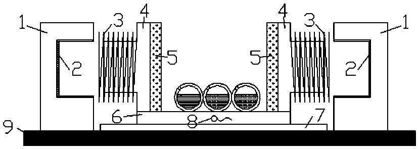
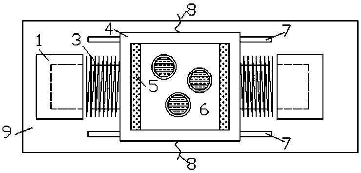
[0020] Embodiment 1: as figure 1 As shown, an embodiment of a particle damper using optimized materials in the present invention mainly includes a baffle plate 1 with a circular groove, a viscous liquid 2, a spring 3, a damper cavity wall 4, a soft Polyurethane foam plastic 5, copper plate 6, guide rail 7, wire 8, magnet 9, hollow ball 10 with holes, rubber 11 and water 12.

[0021] The damper cavity wall 4 is made of non-conductive material such as plastic, and is connected with the lower copper plate 6 by glue or nails. Lubricating oil is coated between the copper plate 6 and the guide rail 7, so that the coefficient of sliding friction between the two is small.

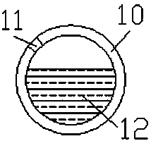
[0022] Such as figure 2 As shown, the granules are composed of hollow spherical balls 10 with holes, rubber 11 and water 12, the rubber 11 is plugged in the holes of the hollow spherical balls 10, and the interior of the hollow spherical balls 10 is filled with water 12. The hollow ball 10 is made of steel with...


PUM


Abstract

The invention relates to a particle damper adopting optimized materials. The particle damper is composed of baffle plates with circular grooves, viscous liquid, springs, damper cavity walls, soft polyurethane foaming plastic, guide rails, a natural magnet, a hollow ball with a hole and rubber. A copper plate is fixed to the lower parts of the damper cavity walls to form a container, and two wiresare arranged on both sides of the copper plate. Cylinders of the cavity walls are sleeved with the springs with a diameter slightly larger than the diameter of each cylinder, and the soft polyurethanefoaming plastic is pasted on the inner sides of the cavity walls. The container is placed on the two guide rails, and the container can slide freely along the guide rails. The baffle plates with thecircular grooves are fixed on both sides of the container. The guide rails and the baffle plates with the circular grooves are all fixed on the magnet. Under the action of wind or / and earthquake, particles can roll and impact in the container, the container can slide on the guide rails, the springs are compressed, the cylinders on the cavity walls can move back and forth in the grooves coated withthe viscous liquid, and the energy of a structure is transferred and dissipated through the impact of the particles, the oscillation of liquid in the particles, the relative movement of the cylindersand viscous liquid and the moving and heating of the copper plate in a magnetic field.

Description

technical field [0001] The invention relates to a particle damper using optimized materials, put particles in a container, and transfer and dissipate them through the impact of particles, the oscillation of the liquid in the particles, the relative motion of the cylinder and the viscous liquid, and the heat generated by the movement of the copper plate in the magnetic field The energy of the structure. At the same time, the wires fixed on the copper plate can be connected with the alarm to remind people in the structure to escape. It belongs to the field of vibration control of civil structures (including high-rise buildings, towering structures and bridge structures, etc.). Background technique [0002] In recent years, passive control technologies such as foundation isolation, energy dissipation and tuning control have been widely used in civil engineering at home and abroad due to their simple concept and clear mechanism. Due to its simplicity, reliability and insensiti...

Claims


Application Information

Patent Timeline
Patent Type & Authority Patents(China)
IPC IPC(8): E04B1/98E04H9/02
CPCE04H9/021E04H9/0215
Inventor 鲁正汪晏李军作
Owner TONGJI UNIV
Why Eureka
Try Eureka