Aircraft heavy oil engine and aircraft

An engine, heavy oil technology, applied in the direction of engine components, machines/engines, mechanical equipment, etc., can solve the problems of insufficient combustion, inability to mix uniformly, engine power, economy and emissions can not be achieved. , The drainage effect is smooth, and the effect of good diversion effect

Pending Publication Date: 2018-08-31
CHONGQING LONCIN ENGINE +1
View PDF0 Cites 1 Cited by
  • Summary
  • Abstract
  • Description
  • Claims
  • Application Information

AI Technical Summary

Problems solved by technology

However, due to the nature of the heavy oil itself, it cannot reach the atomization level of general oil products, and it cannot be mixed evenly with the combustion air. The original EFI ignition method cannot be used when ignition is started; even if the ignition method is used for operation , it will also cause a series of engine problems due to insufficient combustion, unable to achieve reliable atomization of heavy oil and unable to organize efficient combustion of mixed fuel, which makes the power, economy and emission of heavy oil used in engines unable to meet expectations effect, so that the application of heavy oil cannot be widely popularized

Method used


Image

  • Aircraft heavy oil engine and aircraft
  • Aircraft heavy oil engine and aircraft
  • Aircraft heavy oil engine and aircraft

Examples


Embodiment Construction

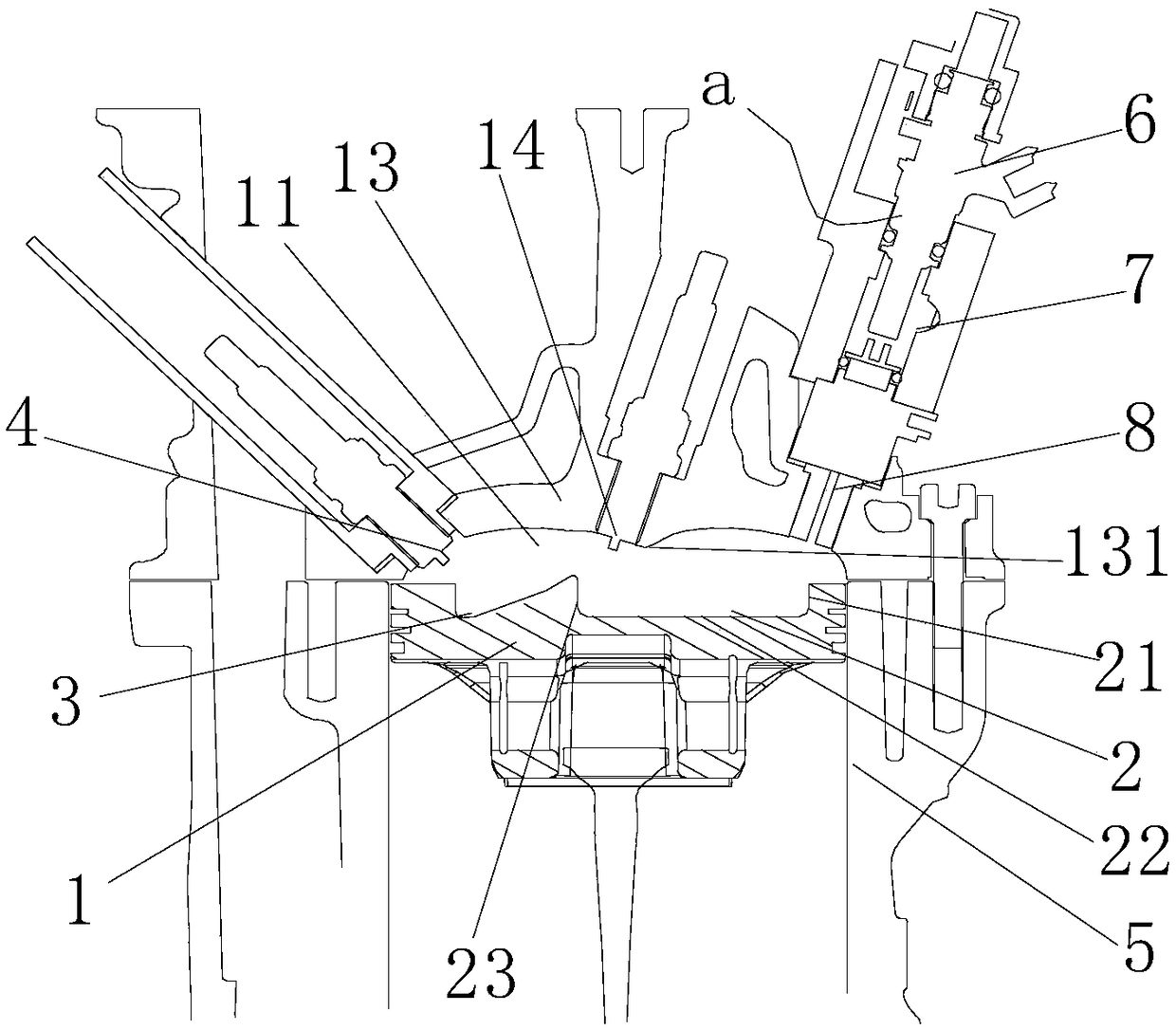
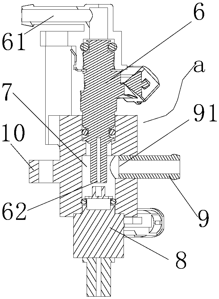
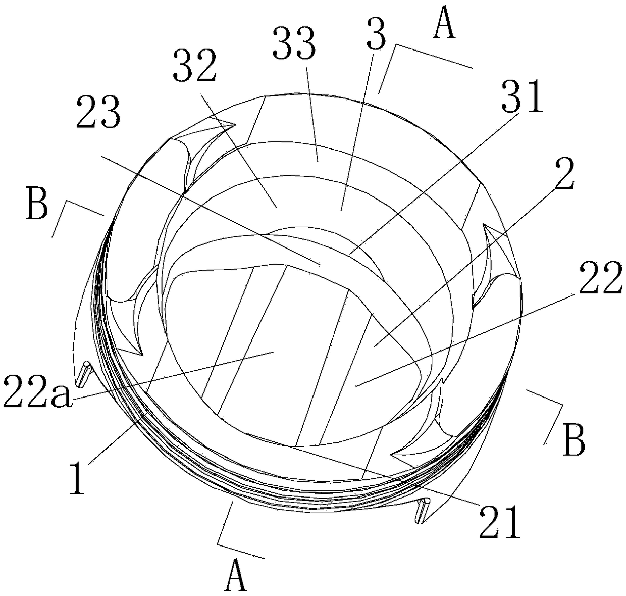
[0023]As shown in the figure: the aviation heavy fuel oil engine of the present embodiment includes a cylinder body 5, a cylinder head 13 and a piston assembly. As shown in the figure, the piston 1 of the piston assembly is located in the cylinder body 5; The fuel injection assembly a where fuel is injected into the combustion chamber; the top surface of the piston 1 forms a concave guide part 2 that is sunken relative to the top surface of the piston; the concave guide part 2 corresponds to the fuel injection direction of the fuel injection assembly, including along The outer surface 21, the bottom 22 and the lead-out surface 23 that smoothly transition from the outside to the inside in the radial direction, the outermost point of the outer surface 21 in the radial direction exceeds or is parallel to the fuel injection direction of the fuel injection assembly (referring to When the fuel assembly injects, and the position of the piston is such that the concave guide corresponds...


PUM


Abstract

The invention discloses an aircraft heavy oil engine and an aircraft. The aircraft heavy oil engine is characterized in that a concave leading part which is sunk relative to the top surface of a piston is formed on the top surface of the piston; the outermost point along the outward radial direction of an outer side surface exceeds or is in flush with the fuel injection direction of a fuel oil injection assembly; the inward radial direction of a leading-out surface exceeds the ignition position of a central spark plug; and an upward-convex strip bulge is formed at a bottom between the outer side surface and the leading-out surface. The aircraft heavy oil engine disclosed by the invention has the beneficial effects that through the concave leading part which is formed on the top surface ofthe piston, corresponds to the injection direction of the fuel oil injection assembly, and is sunk relative to the top surface of the piston, injected fuel can be led to the ignition area of the sparkplug and the top surface of the piston can be optimized; accordingly, a combustion chamber can be optimized, the compression ratio can be changed, and the knocking risk can be reduced; meanwhile, thetumble flow effect can be enhanced, heavy oil can be relatively sufficiently atomized and mixed, and uniform mixed gas for combustion can be formed after the proper mixing operation; and furthermore,the efficient combustion of fuel can be efficiently organized, the power performance, the economic performance and the emission performance of the application of the heavy oil to the engine can be guaranteed, and the energy conservation, the environmental protection and the low cost after the application of the heavy oil to the engine can be achieved.

Description

technical field [0001] The invention relates to an engine and its application, in particular to an aviation heavy oil engine and an aircraft. Background technique [0002] As the fuel for engines, heavy oil will become the power trend of small and medium-sized aircraft; however, heavy oil has high viscosity and poor low-temperature fluidity, which leads to poor atomization effect compared with ordinary light oil, which affects the combustion effect, and even causes difficulty in starting the engine and poor emission. Up to standard. [0003] In the prior art, in order to ensure good atomization and start-up of heavy fuel oil engines, there are fuel supply methods such as carburetor + auxiliary preheating technology, mechanical injection (fuel direct injection), electronically controlled fuel injection, etc. However, due to the nature of the heavy oil itself, it cannot reach the atomization level of general oil products, and it cannot be mixed evenly with the combustion air....

Claims


Application Information

Patent Timeline
IPC IPC(8): F02F3/28F02F3/26F02M61/16F02M61/18
CPCF02F3/26F02F3/28F02M61/162F02M61/1806
Inventor 翟明明石晓东唐程刘小林闪颂武罗晏林成
Owner CHONGQING LONCIN ENGINE
Why Eureka
Try Eureka