Efficiency natural gas directional flow heating system

A directional flow, heating system technology, applied in pipeline systems, pipeline heating/cooling, heat exchange equipment, etc., can solve the problems of low thermal efficiency of LNG recuperators, and achieve the effect of fast heating speed, high thermal efficiency and uniform heating

Pending Publication Date: 2018-08-31
辽宁华燃新能源科技有限公司
View PDF13 Cites 6 Cited by
  • Summary
  • Abstract
  • Description
  • Claims
  • Application Information

AI Technical Summary

Problems solved by technology

[0004] Since the existing LNG reheater uses an electric heater as the heat source and water as the heat medium, that is, the water is heated to 60°C by electric heating first, and then the natural gas in the heat exchange tube is heated to about 60°C by hot water at 60°C. 20°C, so the electric energy is converted into heat energy first, and then transferred to natural gas through hot water as a medium. The energy has been converted and transferred many times, so the thermal efficiency of the LNG reheater is extremely low

Method used


Image

  • Efficiency natural gas directional flow heating system
  • Efficiency natural gas directional flow heating system
  • Efficiency natural gas directional flow heating system

Examples


Embodiment 1

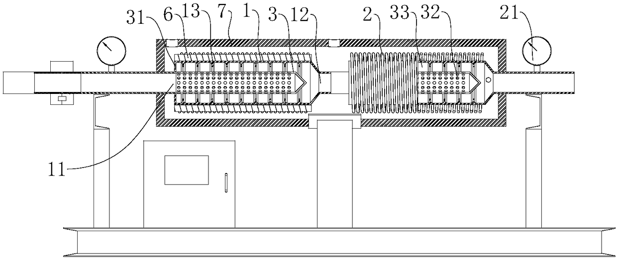
[0032] Example 1: A high-efficiency natural gas directional flow heating system, with a structure such as figure 1 As shown, it includes a regulating module and an induction coil 2 wound on the outside of the heat exchange tube 1. The heat exchange tube 1 includes a natural gas inlet 11 and a natural gas outlet 12. The induction coil 2 heats the heat exchange tube 1. When the natural gas passes through the heat exchange tube 1 , heated by heat exchange tube 1, combined with Figure 4 Look, multiple sets of fins 13 are arranged on the inner wall of the heat exchange tube 1, which can increase the contact area between the natural gas and the high-temperature heat exchange tube 1, thereby improving the heating efficiency of the natural gas. In some cases, multiple sub-stage heat exchange tubes can be combined to form a multi-stage heat exchange, and the induction coil 2 on each heat exchange tube 1 can be independently controlled, so that the adjustment module can regulate the wo...

Embodiment 2

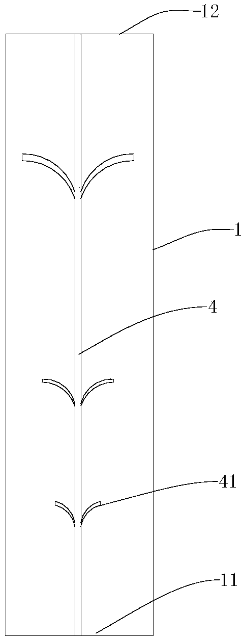
[0039] Embodiment 2: A high-efficiency natural gas directional flow heating system, which differs from Embodiment 1 in that, as image 3 with 4 As shown, the directional flow device includes a fixed rod 4 arranged inside the heat exchange tube 1, and a plurality of flow guides are arranged on the fixed rod 4, and the flow guides include a plurality of arc-shaped guide fins 41, and the arc-shaped guide fins 41 One end is fixedly connected with the fixed rod 4, and the other end extends toward the direction of the heat exchange tube 1. The end of the arc-shaped deflector 41 away from the fixed rod 4 is set close to the natural gas outlet 12, and the outer side of the arc-shaped deflector 41 is close to the fixed rod 4. set up.

[0040] The arc-shaped deflectors 41 in adjacent deflectors are staggered, and the length of the arc-shaped deflectors 41 in the deflectors gradually increases from one end close to the natural gas inlet 11 to the other end. The distance gradually incre...

Embodiment 3

[0043] Embodiment 3: A high-efficiency natural gas directional flow heating system, which differs from Embodiment 1 in that, as Figure 5 As shown, the heat exchange tube 1 includes a first heat exchange tube 8 located inside and a second heat exchange tube 9 located outside, the induction coil 2 is wound on the first heat exchange tube 8, and is located between the first heat exchange tube 8 and the Between the second heat exchange tubes 9, a first channel 81 for natural gas is formed inside the first heat exchange tube 8, and a second channel 91 for natural gas is formed between the tube wall of the second heat exchange tube 9, the first channel 81 for natural gas and the second channel 81 for natural gas The ends of the two channels 91 away from the natural gas inlet 11 communicate with each other, and the end of the second heat exchange tube 9 close to the natural gas inlet 11 is provided with a natural gas outlet 12 communicating with the second natural gas channel 91 .

...


PUM


Abstract

The invention discloses an efficient natural gas directional flow heating system, and relates to the technical field of heating systems. The efficient natural gas directional flow heating system comprises an adjusting module and an induction coil wound outside a heat exchange tube. The heat exchange tube comprises a natural gas inlet and a natural gas outlet, the heat exchange tube is provided with a temperature detection instrument at the natural gas outlet, and the adjusting module detects the temperature according to the temperature detected by the temperature detection instrument to adjustthe working current, power and other parameters of the induction coil. A directional flow device for guiding natural gas to the position of a heat exchange wall is arranged inside the heat exchange tube. According to the scheme, compared with other methods heating from outside, the efficient natural gas directional flow heating system has advantage that the heating speed is fast, the heating timeis only 10% -20% of that of other heating methods, the heating uniformity is high, and the heat efficiency is high.

Description

technical field [0001] The invention relates to the technical field of heating, in particular to a high-efficiency natural gas directional flow heating system. Background technique [0002] The LNG reheater, also known as the LNG secondary heating system, is generally a reheating (secondary heating or supplementary heating) device placed behind the LNG air-temperature vaporizer and before the pressure regulating skid. The theoretical temperature of LNG is about -192°C. After being converted into gaseous natural gas by air-temperature gasifier, due to the influence of environmental temperature and other factors, the temperature of natural gas after gasification is low, which is not satisfactory for users. Reheater is used to treat NG and BOG conducts supplementary heating (secondary heating) to increase the temperature of natural gas to meet user needs. [0003] The LNG reheaters produced in the industry are generally divided into: electric heating water bath reheater (vapor...

Claims


Application Information

Patent Timeline
Patent Type & Authority Applications(China)
IPC IPC(8): F16L53/34F16L59/16F16L59/20F17D1/02
CPCF16L53/34F16L59/16F16L59/166F16L59/168F16L59/20F17D1/02
Inventor 杨柳朱玉孙利迪岑瑾朱科岑孟强王倩
Owner 辽宁华燃新能源科技有限公司
Why Eureka
Try Eureka