Active clamp voltage stress suppression circuit of power switch, active clamp voltage stress suppression method of power switch and driving circuit of power switch
A power switch and stress suppression technology, which is applied in the field of drive circuits and active clamp voltage stress suppression circuits, can solve the problems of TVS service life and current loss that affect the active clamp effect, reduce heat loss and improve utilization rate and improve reliability
- Summary
- Abstract
- Description
- Claims
- Application Information
AI Technical Summary
Problems solved by technology
Method used
Image
Examples
Embodiment 1
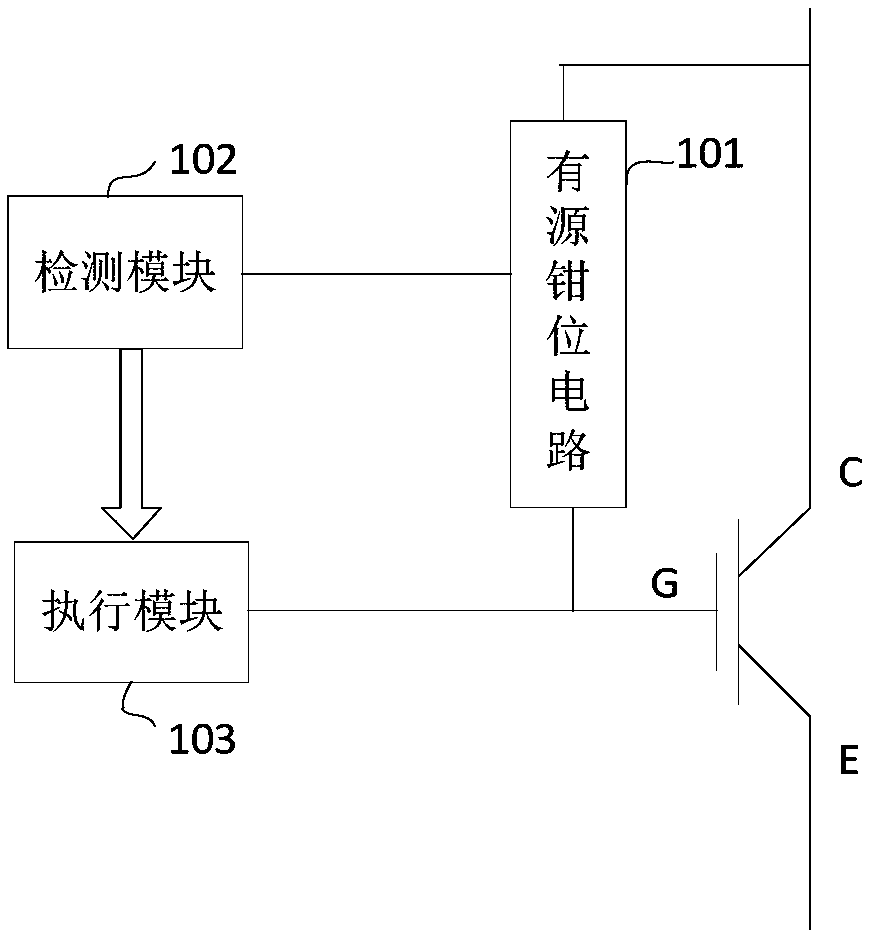
[0046] refer to figure 1 , an active clamping circuit 101 is connected between the input terminal and the control terminal of the power switch, and the power switch is not limited to IGBT, MOSFET and the like. For example, taking an IGBT as an example in this embodiment, the active clamping circuit 101 is connected between the collector and the gate of the IGBT. The active clamp voltage stress suppression circuit of the power switch of the present invention comprises:
[0047] A detection module 102, configured to detect whether the power switch triggers the active clamp;
[0048] The execution module 103 is arranged in the drive path of the power switch, and is used for cutting off the drive path when the detection module 102 detects that the active clamp is triggered.
[0049] It can be understood that when the active clamp is triggered, a current will be injected into the power switch, so it can be determined whether the active clamp is triggered by detecting the magnitud...
Embodiment 2
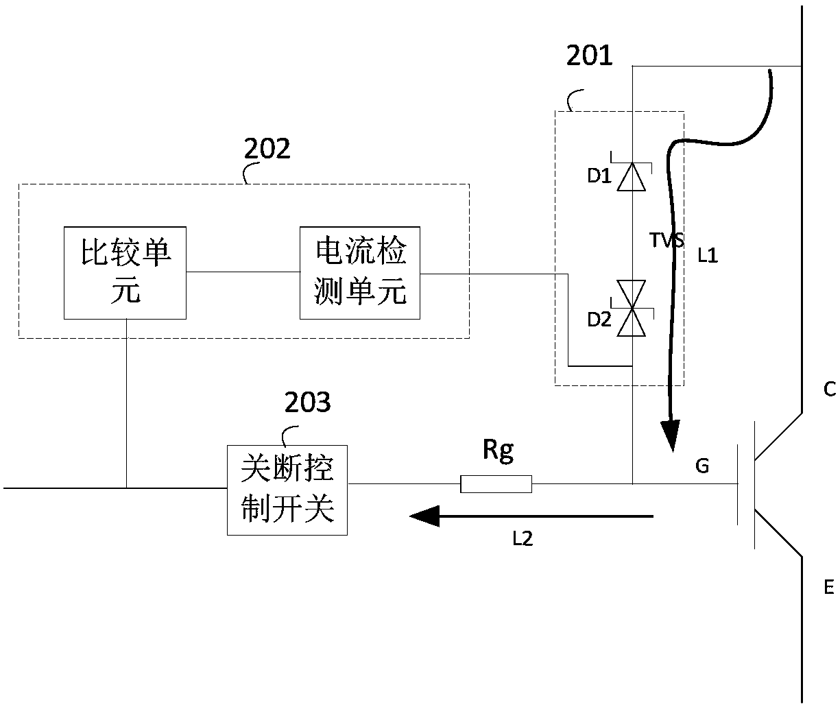
[0054] refer to image 3 , in this embodiment, the active clamp voltage stress suppression circuit of the power switch includes: a detection module 202 and an execution module 203 . Wherein, the detection module 202 includes a current detection unit and a comparison unit, and the execution module 203 includes a turn-off control switch, and the turn-off control switch is set in the current driving path of the power switch. The active clamping circuit 201 includes a unidirectional TVS transistor D1 and a bidirectional TVS transistor D2, and the power switch is an IGBT, specifically:
[0055] The current detection unit is connected between the bidirectional TVS transistor D2 in the active clamping circuit 201 and the gate G of the power switch, and is used to detect the output of the active clamping circuit 201 to the control terminal of the power switch That is, the current of the gate G, and generate a corresponding detection voltage, and the current detection unit can be spec...
Embodiment 3
[0061] refer to Figure 4 , the power switch is IGBT. In this embodiment, the suppression circuit includes: a detection module 302 and an execution module 303 . Wherein, the active clamping circuit 301 includes a unidirectional TVS transistor D1, a bidirectional TVS transistor D2 and a diode D3. The detection module 302 includes a current sampling resistor R1, voltage dividing resistors R2 and R3, a comparator A1, and an analog-to-digital converter C1, and the execution module 303 includes an AND gate C2, a digital-to-analog converter A3, an off control switch K2, and a drive for the power switch The path includes a logic processing unit, a digital-to-analog converter A2, and a conduction control switch K1 for controlling conduction of the power switch.
[0062] Wherein, the first end of the bidirectional TVS transistor D2 is connected to the anode of the diode D3, the cathode of the diode D3 is connected to the control terminal of the power switch, and the second end of the...
PUM
 Abstract
Description
Claims
Application Information
 - R&D
- Intellectual Property
- Life Sciences
- Materials
- Tech Scout
- Unparalleled Data Quality
- Higher Quality Content
- 60% Fewer Hallucinations
Browse by: Latest US Patents, China's latest patents, Technical Efficacy Thesaurus, Application Domain, Technology Topic, Popular Technical Reports.
© 2025 PatSnap. All rights reserved.Legal|Privacy policy|Modern Slavery Act Transparency Statement|Sitemap|About US| Contact US: help@patsnap.com


