Process detecting device used in machine manufacturing

A process detection and mechanical manufacturing technology, applied in the direction of manufacturing tools, metal processing machinery parts, measuring/indicating equipment, etc., can solve the problems of slow debugging, cutting, and adjustment in one step, so as to ensure stability, Ensure coaxiality and ensure the effect of precision requirements

Active Publication Date: 2018-09-04
XUAZHOU HEIBAILONG ENG NYLON
View PDF8 Cites 18 Cited by
  • Summary
  • Abstract
  • Description
  • Claims
  • Application Information

AI Technical Summary

Problems solved by technology

[0002] At present, in the field of gear processing, gear hobbing is the most important link, which directly affects the progress of subsequent processes. In the process of gear hobbing, the span distance of hobbing will change due to the influence of machine tool accuracy and temperature. , At this time, it is necessary to re-measure the span distance and then adjust the program according to the span distance measurement. It is difficult to complete the adjustment process in one step, and it needs to be debugged step by step. After the hobbing is clamped, due to the reason of the measuring ball, It is necessary to remove the workpiece from the fixture for measurement, because repeated clamping will cause rotten teeth and knife damage. Generally, unqualified workpieces cannot be processed and tested again, which wastes resources, and there are also cases where the workpiece is not removed for measurement. The method is to smear butter on the measuring ball, so that the measuring ball is absorbed in the tooth surface. This measurement method is difficult to operate and the measurement is not accurate.

Method used


Image

  • Process detecting device used in machine manufacturing
  • Process detecting device used in machine manufacturing
  • Process detecting device used in machine manufacturing

Examples


Embodiment Construction

[0014] The following will clearly and completely describe the technical solutions in the embodiments of the present invention with reference to the accompanying drawings in the embodiments of the present invention. Obviously, the described embodiments are only some, not all, embodiments of the present invention. Based on the embodiments of the present invention, all other embodiments obtained by persons of ordinary skill in the art without making creative efforts belong to the protection scope of the present invention.

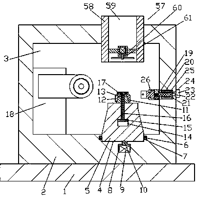
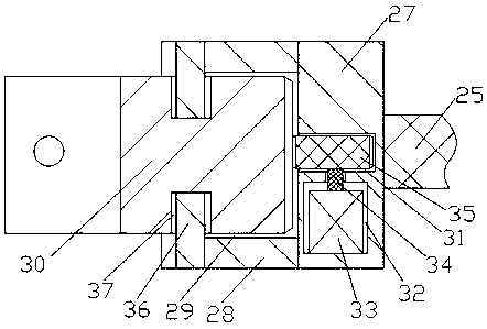
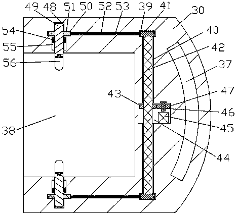
[0015] see Figure 1-4, an embodiment provided by the present invention: a process detection device in mechanical manufacturing, including a fixed base plate 1, the upper end surface of the fixed base plate 1 is provided with a CNC cabinet 2 with an integrated structure, and the inside of the CNC cabinet 2 A processing space 3 is provided, and the right side of the lower end wall of the processing space 3 is provided with a clamp groove 4, and a clamp body 5 i...


PUM


Abstract

The invention discloses a process detecting device used in machine manufacturing. The process detecting device comprises a fixed base plate, a numerical control machine case is arranged on the upper end face of the fixed base plate, the numerical control machine case and the fixed base plate are of an integrated structure, a clamp body is arranged in a clamp groove, a taper shaft is fixedly connected to the middle position of the upper end face of the clamp body, the upper side of the taper shaft is sleeved with an expanding sleeve, a hob module is fixedly arranged at the left end of the interior of a machining space, and the left end of a stretchable rod penetrates out of the left end wall of a stretchable space and a stretchable groove and is fixedly connected with an across-measured distance detecting device. When the process detecting device works, a dividing groove guarantees that the expanding sleeve can expand towards the periphery evenly, the coaxality is guaranteed, the accuracy requirement in the machining process is guaranteed, the measurement angle is automatically adjusted, and the accuracy of a measurement value is guaranteed; and in the measurement process, workpieces in machining do not need to be detached, tooth breaking caused by repeated clamping is avoided, machining materials are saved, and the technological controllability is increased.

Description

technical field [0001] The invention relates to the field of processing process control, in particular to a process detection device in mechanical manufacturing. Background technique [0002] At present, in the field of gear processing, gear hobbing is the most important link, which directly affects the progress of subsequent processes. In the process of gear hobbing, the span distance of hobbing will change due to the influence of machine tool accuracy and temperature. , At this time, it is necessary to re-measure the span distance and then adjust the program according to the span distance measurement. It is difficult to complete the adjustment process in one step, and it needs to be debugged step by step. After the hobbing is clamped, due to the reason of the measuring ball, It is necessary to remove the workpiece from the fixture for measurement, because repeated clamping will cause rotten teeth and knife damage. Generally, unqualified workpieces cannot be processed and t...

Claims


Application Information

Patent Timeline
Patent Type & Authority Applications(China)
IPC IPC(8): B23Q17/20
CPCB23Q17/20
Inventor 朱林祥
Owner XUAZHOU HEIBAILONG ENG NYLON
Why Eureka
Try Eureka