
Electroosmosis sludge treatment device

A sludge treatment and electro-osmosis technology, applied in electrochemical sludge treatment, sludge treatment, water/sludge/sewage treatment, etc., can solve problems such as high energy consumption

Pending Publication Date: 2018-09-04
CHINA JILIANG UNIV
View PDF3 Cites 3 Cited by
  • Summary
  • Abstract
  • Description
  • Claims
  • Application Information

AI Technical Summary

Problems solved by technology

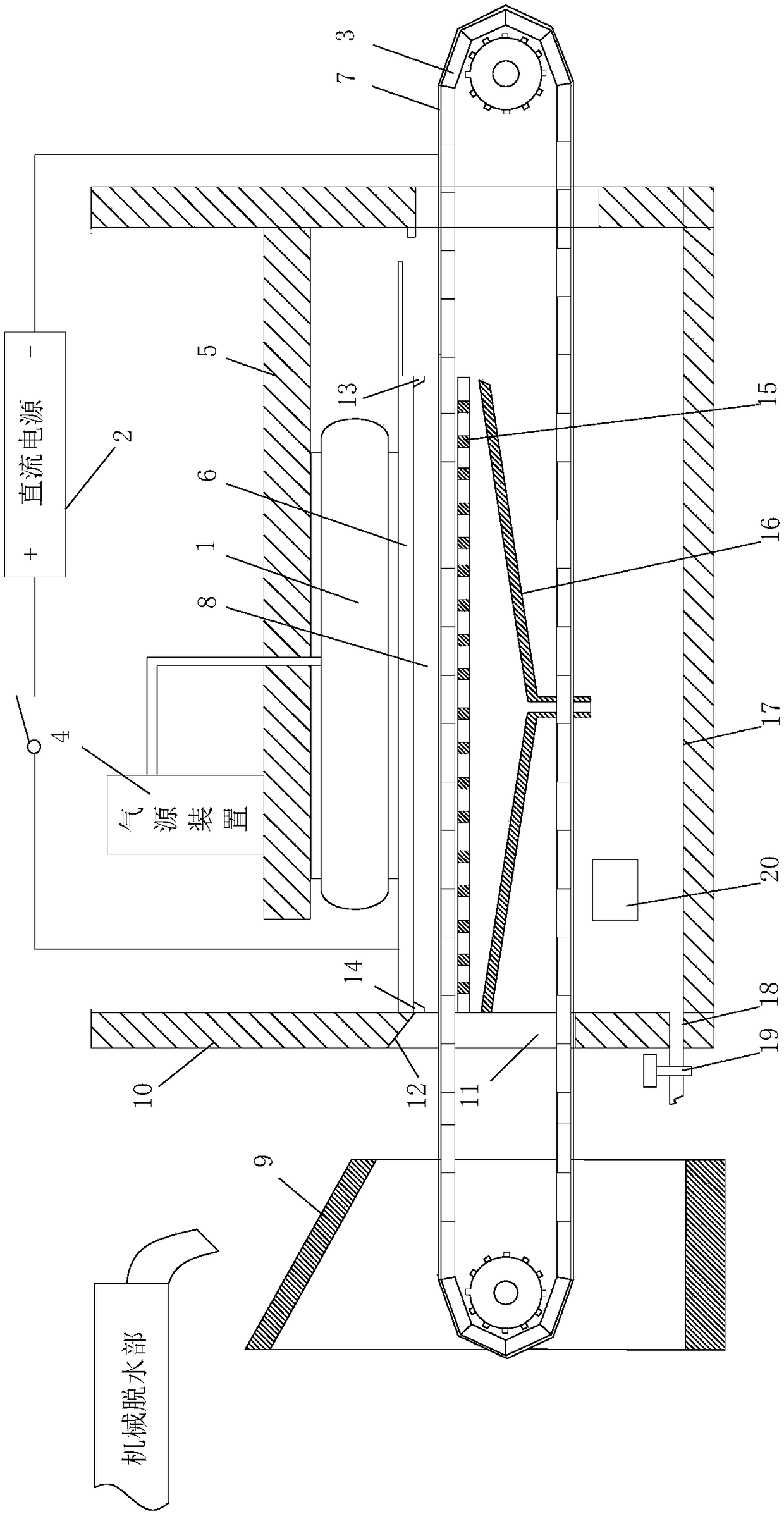
[0003] The present invention aims to provide an electroosmotic sludge treatment device to solve the problem of high energy consumption in the electroosmotic dehydration process of the existing technical solutions

Method used


Image

  • Electroosmosis sludge treatment device
  • Electroosmosis sludge treatment device

Examples


Embodiment 1

[0029] The invention provides an electroosmotic sludge treatment device, such as figure 1 and figure 2 As shown, it includes an electroosmosis dehydration part, and the electroosmosis dehydration part includes an air spring 1, a DC power supply 2, a conveyor belt 3, an air source device 4 connected to the air spring 1 for charging and deflation of the air spring 1, and for fixing The fixed portion 5 of the air spring 1, the upper end of the air spring 1 is fixedly connected to the fixed portion 5, the lower end of the air spring 1 is provided with an electrode plate 6, and the electrode plate 6 is connected to the positive stage of the DC power supply 2; The conveyor belt 3 is arranged below the electrode plate 6, and the outer surface of the conveyor belt 3 is covered with a metal filter screen 7, and the metal filter screen 7 is connected to the negative pole of the DC power supply 2 device; the electrode plate 6 is located directly below the electrode plate 6 A dewatering...

Embodiment 2

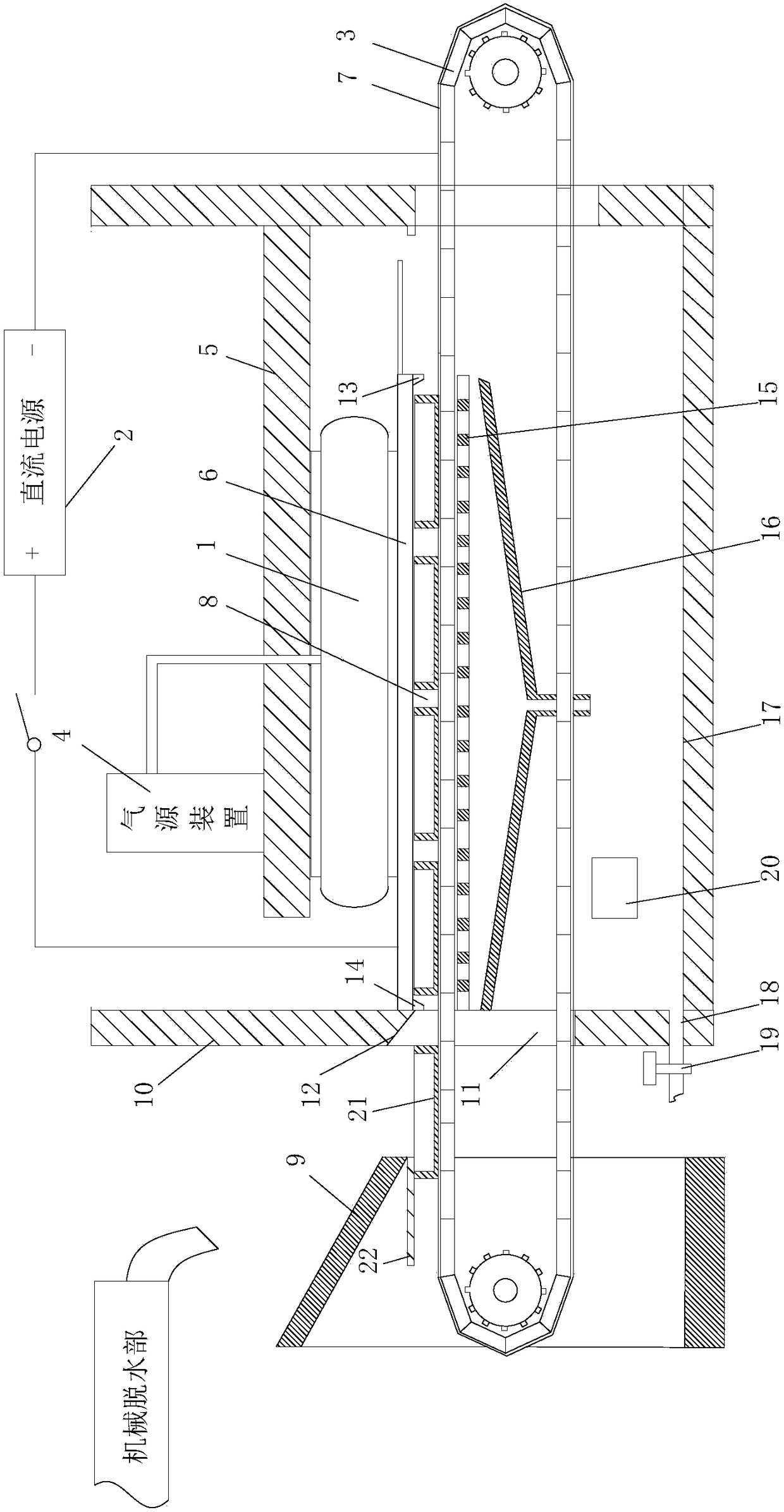
[0037] Such as figure 2 As shown, the difference from Example 1 is that the electrode plate is provided with an electromagnetic field pressurization device for pressurizing the sludge and an ultrasonic vibration device (not shown) for shaking the sludge, and the electromagnetic field pressurization Both the device and the ultrasonic vibration device can be products in the prior art; the present invention will not be described in detail.

[0038] Further, the conveyor belt is provided with a number of drawer-type mud pressing boards 21 evenly distributed along the moving direction of the conveyor belt. The bottom of the drawer-type mud pressing boards 21 is provided with a cathode electrode plate, and a mud guard is provided below the mud inlet slideway. device 22, the bottom of the mudguard device 22 is flat with the top of the drawer type mud pressing plate 21; the cathode electrode plate is connected with the negative pole of the DC power supply device. Wherein, as an opti...


PUM


Abstract

The invention aims to provide an electroosmosis sludge treatment device to solve the problem of high energy consumption in an electroosmosis dewatering process of an existing technical scheme. The electroosmosis sludge treatment device comprises an electroosmosis dewatering part, wherein the electroosmosis dewatering part comprises an air spring, a direct current power supply, a conveying belt, anair source device which is connected with the air spring and is used for inflating and deflating the air spring, and a fixing part for fixing the air spring; the upper end of the air spring is fixedly connected with the fixing part, and the lower end of the air spring is provided with an electrode plate; the electrode plate is connected with a positive electrode of the direct current power supply; the conveying belt is arranged below the electrode plate; a metal filter net is laid on the outer surface of the conveying belt; the metal filter net is connected with a negative electrode of the direct current power device; a dewatering cavity for accommodating sludge is formed between the electrode plate and the conveying belt under the electrode plate. In a sludge dewatering process, in caseof changes in the thickness of sludge, the sludge still can be stressed by the acting force of the air spring without inflating the air spring by the air source device, thereby reducing the energy consumption.

Description

technical field [0001] The invention relates to the field of environmental protection, in particular to an electroosmotic sludge treatment device. Background technique [0002] Electro-osmosis dehydration drying technology is a newly developed sludge dewatering technology, which organically combines solid-liquid separation technology and physical and chemical treatment technology with electrochemical properties of sludge itself, and uses "electricity" for dehydration. It has many characteristics that are not found in various dehydration treatment technologies, and it can reduce the water content of activated surplus sludge to below 60%, which is difficult to achieve by other mechanical dehydration methods. The dewatering effect of biochemical sludge is particularly obvious. The existing electroosmotic dehydration device generally includes a mechanical dehydration part and an electroosmotic dehydration part. The electroosmotic dehydration part includes an anode plate and a c...

Claims


Application Information

Patent Timeline
Patent Type & Authority Applications(China)
IPC IPC(8): C02F11/12C02F11/00
CPCC02F11/006C02F11/12
Inventor 卢锡龙饶宾期万延见张岩赵子恺
Owner CHINA JILIANG UNIV
Learn More