A rotary UV exposure machine

A technology of exposure machine and ultraviolet light source, which is applied in the fields of optomechanical equipment, microlithography exposure equipment, photolithographic process exposure device, etc. The effect of strong performance, large processing size and high processing efficiency

Active Publication Date: 2020-12-22
合肥泰沃达智能装备有限公司
View PDF7 Cites 0 Cited by
  • Summary
  • Abstract
  • Description
  • Claims
  • Application Information

AI Technical Summary

Problems solved by technology

For surface exposure, it is more difficult to use upper exposure than lower exposure. The upper exposure mask is on the top of the coating layer. It is necessary to ensure the distance between the coating layer and the mask. The coating layer cannot touch the mask, and the spacing should not exceed Large, the graphics accuracy is not high when the spacing is too large
In the upper exposure method, the mask is easily polluted due to the volatilization of the solvent during the exposure process, the cleaning times of the mask increase, and the scrap rate of the mask is high
The single-point exposure machine uses the lens to focus light and process the graphics through point-line exposure according to the drawn graphics. This exposure method does not require a mask, and can also perform upper exposure, but this method is mainly used in small sizes, generally 10 inches. The following; because this kind of exposure is single-point linear processing, the processing speed is very slow, so the size limitation and processing speed of this exposure machine are limited

Method used


Image

  • A rotary UV exposure machine
  • A rotary UV exposure machine

Examples


Embodiment Construction

[0022] The purpose of the present invention can be achieved through the following technical solutions:

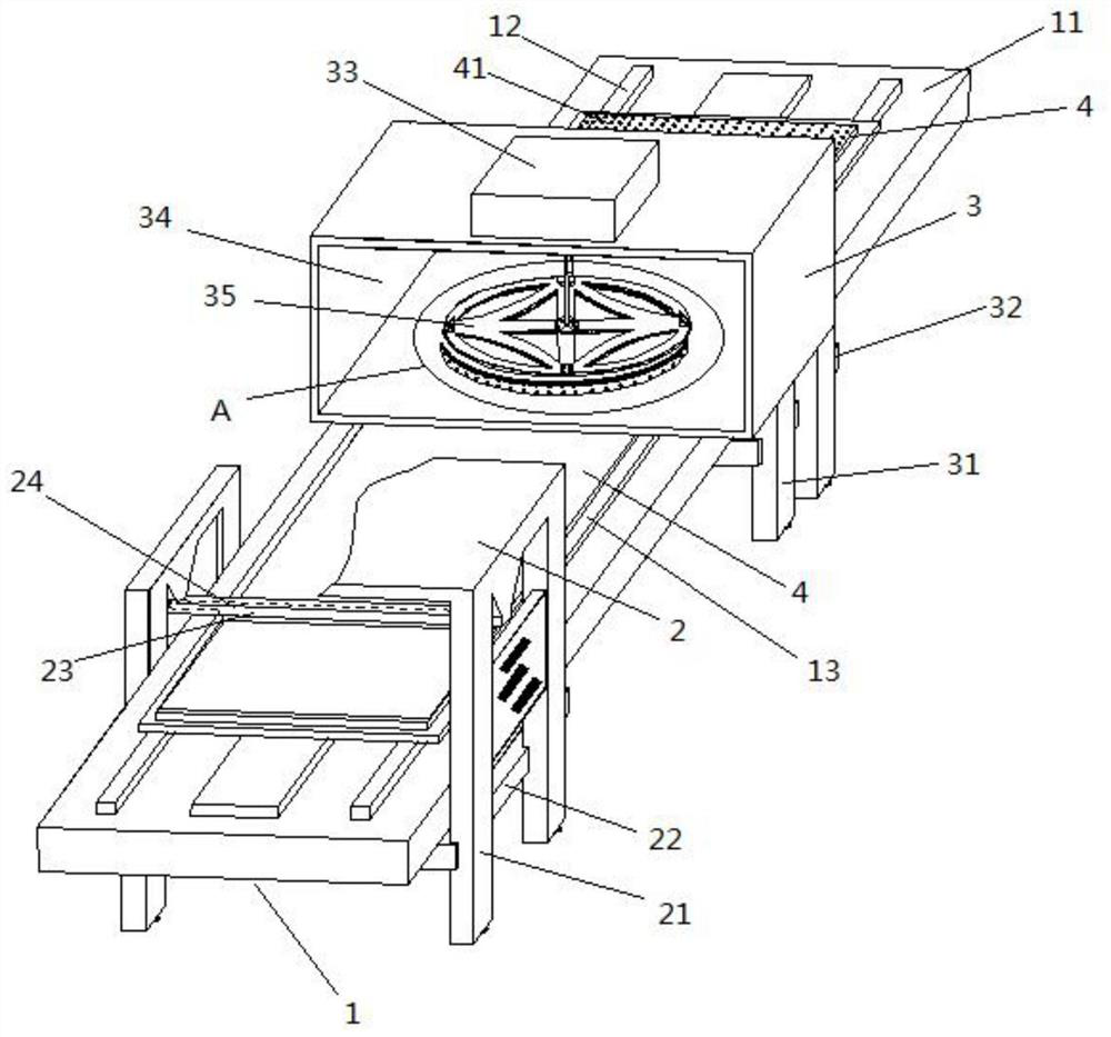
[0023] A rotary ultraviolet exposure machine, see Figure 1-2 , including transfer table 1, coating machine 2, exposure machine 3;

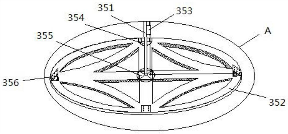
[0024] The coating machine 2 is located on one side of the exposure machine 3, and the transfer table 1 passes through the coating machine 2 and the exposure machine 3 in turn, and an ultraviolet light source generator 33 is arranged on the top of the exposure machine 3; an exposure cavity 34 is arranged in the middle of the exposure machine 3 , the exposure cavity 34 is provided with a rotary exposure device 35, and the rotary exposure device 35 is connected to the ultraviolet light source generator 33 through a light source injector 353;

[0025] The lower surface of the transfer table 1 is installed on the first base beam 22 and the second base beam 32, the first base beam 22 is arranged on the coating anti-vibration base 21 below the coat...


PUM


Abstract

The invention discloses a rotary ultraviolet exposure machine. The rotary ultraviolet exposure machine comprises a conveyer table, a coating machine and an exposure machine, wherein the coating machine is located on one side of the coating machine, the conveyer table sequentially penetrates through the coating machine and the exposure machine, and an ultraviolet light source generator is arrangedat the top of the exposure machine; an exposure cavity is formed in the middle of the exposure machine, a rotary exposer is arranged on the exposure cavity and is connected to the ultraviolet light source generator through a light source; a first base crossbeam and a second base crossbeam are mounted on the lower surface of the conveyer table, and the first base crossbeam is arranged on a coatingquakeproof base below the coating machine; and the second base crossbeam is arranged on an exposure quakeproof base below the exposure machine. The rotary ultraviolet exposure machine has the characteristics that an exposure mask plate is not required, the machining speed is high, the machining efficiency is high, the machining size is large, and the machining compatibility is strong.

Description

technical field [0001] The invention relates to a rotary ultraviolet exposure machine, in particular to a rotary ultraviolet exposure machine which does not require a mask plate for exposure, has high processing speed, high processing efficiency, large processing size and strong processing compatibility. Background technique [0002] The photolithography processing method of the dots of the light guide plate includes: laser dot processing, ink dot processing, hot press dot processing, ink dot processing, coating the ink on the processing surface of the light guide plate, and then exposing the ink on the processing surface of the light guide plate through an exposure machine . [0003] The lithography process of the dots of the light guide plate requires the use of coating and exposure, which belong to two processes and equipment, and the processing section is long; uncertain factors are prone to occur during processing, the defect rate is also high, and the processing time i...

Claims


Application Information

Patent Timeline
Patent Type & Authority Patents(China)
IPC IPC(8): G03F7/20
CPCG03F7/2004G03F7/2008G03F7/70058G03F7/7015
Inventor 覃佐波刘莎莉
Owner 合肥泰沃达智能装备有限公司
Why Eureka
Try Eureka