Novel differential- and common-mode filter inductance structure

A technology of common-mode filtering and inductance, which is applied in the field of new differential common-mode filter inductance structures, can solve the problems that filter inductance cannot be applied to high-current occasions, additionally set a magnetic conductive layer, and high production costs, and achieves easy modular design and convenient power consumption. Extended and consistent effects

Inactive Publication Date: 2018-09-04
BEIJING INST OF SPACE LAUNCH TECH +1
View PDF7 Cites 6 Cited by
  • Summary
  • Abstract
  • Description
  • Claims
  • Application Information

AI Technical Summary

Problems solved by technology

[0005] In order to solve the problems that existing filter inductors with ring magnetic core structure cannot be applied to high current occasions, need additionally set up a magnetic permeable layer, have poor consistency and high production costs, the present invention innovatively provides a novel differential common-mode filter inductor structure , compl

Method used


Image

  • Novel differential- and common-mode filter inductance structure
  • Novel differential- and common-mode filter inductance structure
  • Novel differential- and common-mode filter inductance structure

Examples


Embodiment Construction

[0027] A novel differential common-mode filter inductor structure involved in the present invention will be explained and described in detail below in conjunction with the accompanying drawings.

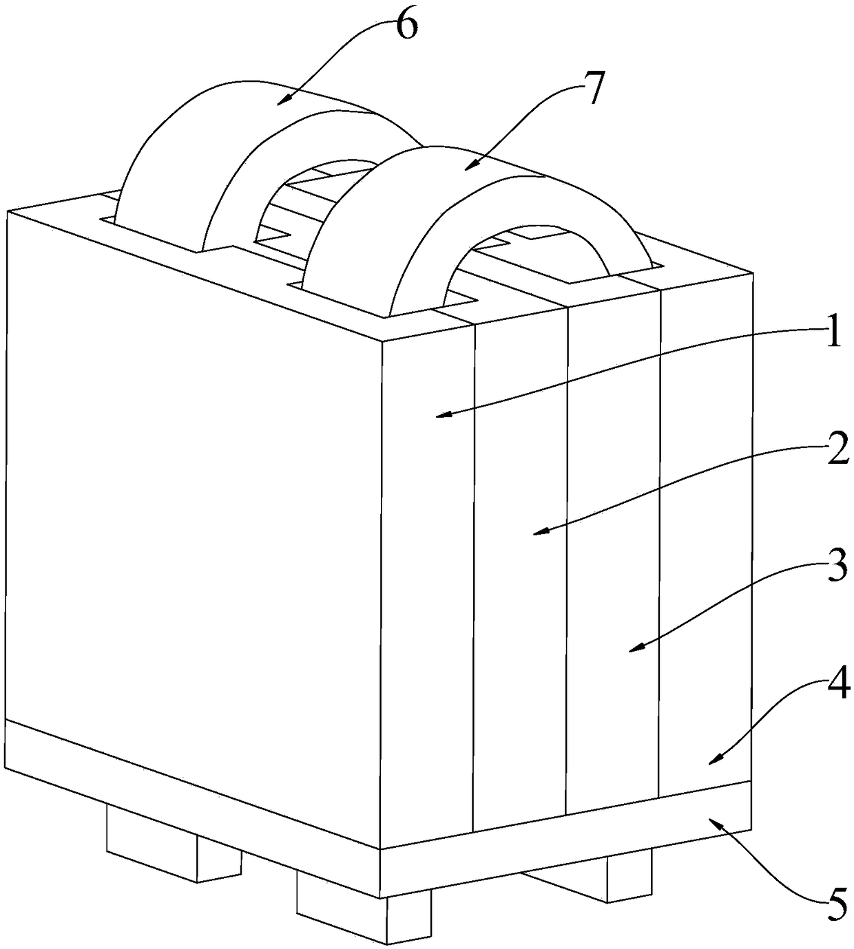
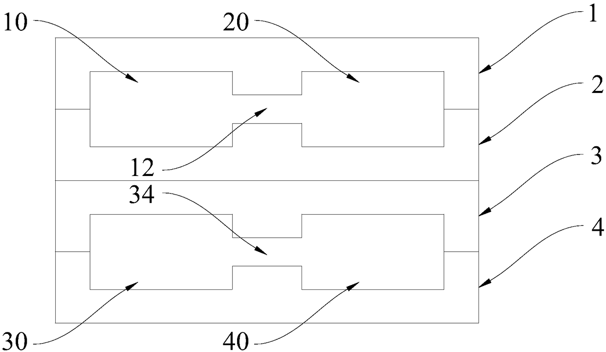
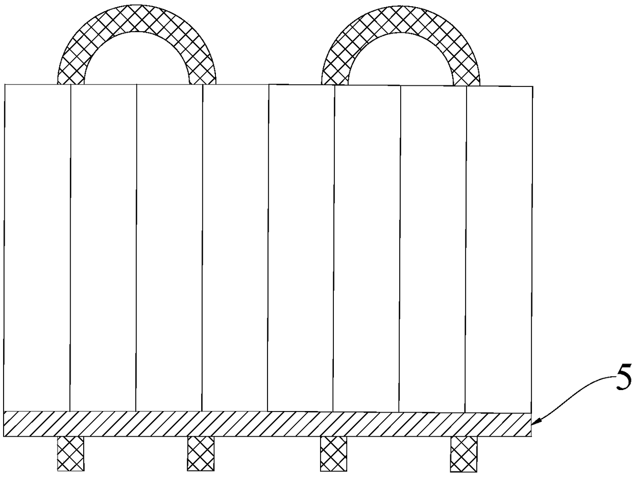
[0028] Such as figure 1 , 2 , 3, in order to solve the problems existing in existing filter inductors such as only applicable to small current occasions, poor consistency, difficulty in mass production, and high production costs, this embodiment discloses a new type of differential common-mode filter inductor structure, which can effectively solve current problems. There are many problems in the filter inductor with ring magnetic core structure, which are explained in detail as follows.

[0029] The differential common mode filter inductor structure disclosed in this embodiment includes a first magnetic core 1, a second magnetic core 2, a third magnetic core 3, a fourth magnetic core 4, a first copper strip 6 and a second copper strip 7; figure 1 As shown, the first magnetic core 1...


PUM


Abstract

The invention discloses a novel differential- and common-mode filter inductor structure. The filter inductor structure comprises a first magnetic core, a second magnetic core, a third magnetic core, afourth magnetic core, a first copper strip and a second copper strip, wherein the first magnetic core is attached onto the second magnetic core, a first through hole and a second through hole are simultaneously formed between the first magnetic core and the second magnetic core and communicate with each other via a first air gap, the third magnetic core is attached onto the fourth magnetic core,a third through hole and a fourth through hole are simultaneously formed between the third magnetic core and the fourth magnetic core and communicate with each other via a second air gap, the first copper strip and the second copper strip are used as windings, the first copper strip penetrates through the second through hole and the fourth through hole, and the second copper strip penetrates through the first through hole and the third through hole. The differential- and common-mode filter has the advantages of compact structure, high current through capability and good filtering performance,moreover, filtering characteristics can be configured, and modular expansion can be performed.

Description

technical field [0001] The invention relates to the technical field of inductance elements, and more specifically, the invention is a novel differential common-mode filter inductance structure. Background technique [0002] During the high-frequency switching operation of the switching power supply, serious conducted electromagnetic interference (EMI) will be generated, and EMI will affect the normal operation of other electronic equipment. Therefore, it is necessary to use EMI filters at the input and output of the switching power supply. The main electronic components of an EMI filter include: differential mode inductors and common mode inductors. In order to meet the requirement of a smaller power supply volume, the differential mode inductor and the common mode inductor are often integrated to obtain a differential common mode filter inductor. [0003] At present, the conventional differential common-mode filter inductor structure often uses a ring core. However, the ...

Claims


Application Information

Patent Timeline
IPC IPC(8): H01F27/24H01F27/28H01F17/00H01F17/04
CPCH01F17/00H01F17/04H01F27/24H01F27/2847H01F2017/0093
Inventor 谭文华张昊东王建军李均锋鞠兴龙申宏伟
Owner BEIJING INST OF SPACE LAUNCH TECH
Why Eureka
Try Eureka