Floating power supply rail applicable to GaN high-speed gate driving circuit

A technology of gate drive circuit and floating power supply, applied in the direction of high-efficiency power electronic conversion, circuits, electrical components, etc., can solve the problems of insufficient dynamic range, difficult design of high-speed and high-power half-bridge gate drive circuits, and increased transmission delay of drive signals.

Active Publication Date: 2018-09-04
UNIV OF ELECTRONICS SCI & TECH OF CHINA
View PDF5 Cites 21 Cited by
  • Summary
  • Abstract
  • Description
  • Claims
  • Application Information

AI Technical Summary

Problems solved by technology

But because the bootstrap capacitor C boot The voltage difference between the upper and lower plates V BST -V SW Clamped within 5.5V to ensure safe operation, and the dead time power stage bias voltage V SW large negative value, the bootstrap capacitor C boot coupling effect, the floating power rail BST level will follow the power stage bias voltage V SW Entering the negative voltage is much lower than 5V, which brings new problems: 1. The dynamic range of the low-voltage to high-voltage level shift circuit (Level Up) that connects the power tube control circuit and the low-voltage logic circuit on the bridge is not enough (low-voltage to high-voltage level shift circuit). The power rail of the high-voltage level shift circuit is generally a floating power rail (BST and chip ground), which causes the response speed of the low-voltage to high-voltage level shift circuit (Level Up) to fail to meet the high-speed requirements, and the transmission delay of the driving signal increases; 2. After The threshold level of the stage logic circuit will decrease with the synchronous decline of the floating power supply rail BST and the low voltage power supply rail SW potential during the dead time, and at the same time, due to the reduction of the dynamic range of the low voltage to high voltage level shift circuit (Level Up) It will cause the amplitude of the driving signal to decrease after passing through the level shift. These two phenomena will cause the input signal to not be recognized by the subsequent logic circuit during transmission and signal loss will occur.
The above problems have brought difficulties to the design of high-speed and high-power half-bridge gate drive circuits suitable for GaN power switching devices, making it difficult to implement GaN power switching devices that can work within a safe voltage and low-voltage to high-voltage level shift circuits ( Level Up) floating rail with sufficient dynamic range

Method used


Image

  • Floating power supply rail applicable to GaN high-speed gate driving circuit
  • Floating power supply rail applicable to GaN high-speed gate driving circuit
  • Floating power supply rail applicable to GaN high-speed gate driving circuit

Examples


Embodiment Construction

[0043] The technical scheme of the present invention is described in detail below in conjunction with accompanying drawing and specific embodiment:

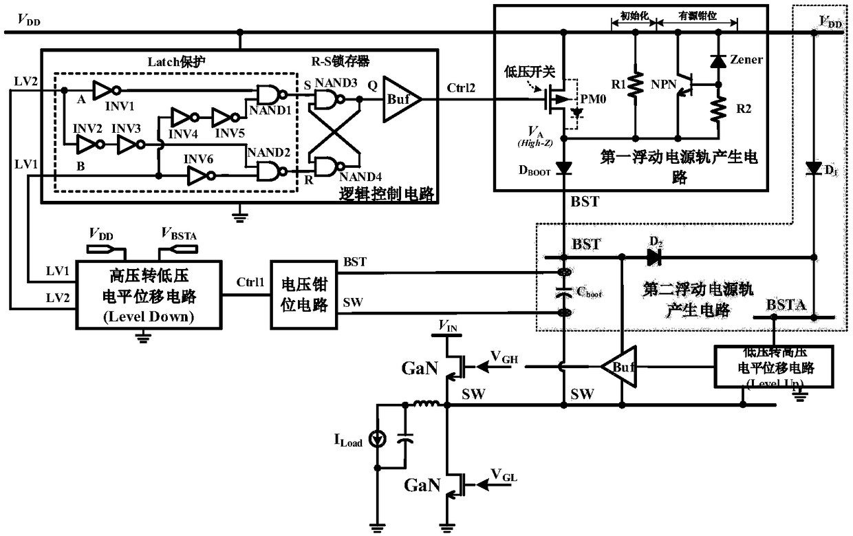
[0044] The floating power rail suitable for the GaN high-speed gate drive circuit proposed by the present invention adopts the design of double floating power rails, and the high-voltage to low-voltage level shift circuit, the voltage clamping circuit, the logic control circuit and the first floating power rail generation circuit form a closed loop. It is used to generate the first power rail BST; the two floating power rail generating circuits form an open loop and is used to generate the second power rail BSTA.

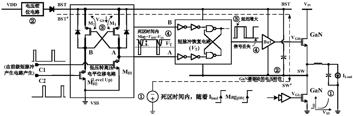
[0045] The power rails of the snubber circuit in the GaN high-speed gate drive circuit are the first floating power rail BST and the half-bridge switching node power rail SW protected by the voltage difference clamp of the bootstrap capacitor Cboot, which can protect the gate-source voltage of the GaN power switching de...


PUM


Abstract

The invention relates to a floating power supply rail applicable to a GaN high-speed gate driving circuit, and belongs to the technical field of power management. With the design of dual floating power supply rails, a GaN power switch device can work within a safety voltage, and a low-voltage-to-high-voltage potential displacement circuit has enough dynamic range. A high-voltage-to-low-voltage potential displacement circuit, a voltage clamping circuit, a logic control circuit and a first floating power supply rail generation circuit form a closed loop, a BST for generating a first power supplyrail is used as a power supply rail of a buffer circuit in the GaN high-speed gate driving circuit, and a gate source voltage of the GaN power switch device can be enabled to be within a safety range; and a second floating power supply rail generation circuit forms a closed loop, a BSTA for generating a second power supply rail is used as a power supply rail of the low-voltage-to-high-voltage potential displacement circuit in the GaN high-speed gate driving circuit, and the GaN high-speed gate driving circuit can be enabled to have enough dynamic range.

Description

technical field [0001] The invention belongs to the technical field of power management, and in particular relates to a floating power rail suitable for a GaN high-speed gate drive circuit. Background technique [0002] With the development of power electronics in recent years, half-bridge drive circuits are developing towards high power and high frequency, which also brings new requirements to the selection of power tubes and circuit design. Traditional half-bridge drive circuits mainly use silicon power transistors as the power stage. In contrast, GaN power switch devices (such as GaN HEMT) have good physical characteristics such as high voltage resistance and no reverse recovery time, so GaN power switches are used. The half-bridge gate drive circuit of the device has excellent characteristics such as high speed and high power density. However, when an enhanced GaN power switching device (GaN HEMT is used as an example below) is used as the power tube of the half-bridge ...

Claims


Application Information

Patent Timeline
Patent Type & Authority Applications(China)
IPC IPC(8): H02M1/088H03K17/081H03K17/687
CPCH02M1/088H03K17/08104H03K17/6871Y02B70/10
Inventor 明鑫张宣范子威秦尧胡黎潘溯张春奇王卓张波
Owner UNIV OF ELECTRONICS SCI & TECH OF CHINA
Why Eureka
Try Eureka