Signal modulation and demodulation device and method in space X-ray communication

A technology of modulation and demodulation and X-ray, which is applied in the field of space communication, can solve the problems of large photon number determination threshold, large influence of background noise, and limitation of the number of symbols, so as to increase the amount of communication information, reduce background noise interference, The effect of reducing bit error rate

Active Publication Date: 2018-09-04
NANJING UNIV OF AERONAUTICS & ASTRONAUTICS
View PDF6 Cites 20 Cited by
  • Summary
  • Abstract
  • Description
  • Claims
  • Application Information

AI Technical Summary

Problems solved by technology

[0005] The limitations of this method are: 1) the number of code elements is limited, and only two code elements "0" and "1" can be loaded according to the presence / absence of X-ray generation; 2) the background noise has a large impact on photons at the detection end During detection, the number of photons in the full spectrum is detected. In order to effectively avoid the influence of background noise on the bit error rate, the threshold for judging the number of photons is required to be large.
[0006] The above X-ray communication systems are all based on the intensity modulation method. In this method, the number of signal symbols is limited to a certain extent. At the detection end, it is necessary to detect photons in the full energy range, and the signal-to-noise ratio is low. In each discrimination cycle, a higher Photon Counting to Guarantee Bit Error Rate Parameters

Method used


Image

  • Signal modulation and demodulation device and method in space X-ray communication
  • Signal modulation and demodulation device and method in space X-ray communication
  • Signal modulation and demodulation device and method in space X-ray communication

Examples


Embodiment Construction

[0026] The present invention is described in further detail now in conjunction with accompanying drawing.

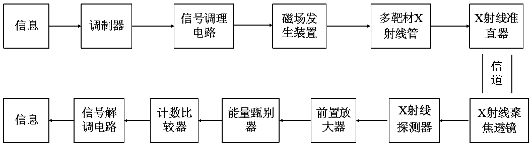
[0027] Such as figure 1 The signal modulation and demodulation device in the space X-ray communication shown includes a modulator, a signal conditioning circuit, a magnetic field generator, a multi-target X-ray tube, an X-ray collimator, an X-ray focusing lens, an X-ray detector, Preamplifier, energy discriminator, counting comparator, signal demodulation circuit.

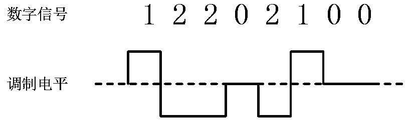
[0028] Such as figure 2 As shown, the modulator encodes and modulates the information, and loads three digital signal symbols, which are "0", "1" and "2". The signal conditioning circuit generates different levels according to the symbol type to input to the magnetic field generating device, and the input levels include negative level, zero level and positive level. The digital signal code "0" corresponds to the negative level, which corresponds to the generation of the first characteristic photon; the co...


PUM


Abstract

The invention discloses a signal modulation and demodulation device and method in space X-ray communication. Information is coded and modulated into high and low levels. The high and low levels are input into a magnetic field generation device to generate a modulation magnetic field. Electrons in a multi-target material X-ray tube bombard different target materials to generate characteristic X rays. The characteristic X rays are emitted. Characteristic X-ray photons with different energy are taken as information carriers. The information carriers are received by an X-ray detector. Detection signals pass a preamplifier and then are input into an energy discriminator. Energy discrimination is carried out on the characteristic X-ray photons. The characteristic X-ray photons are counted by counters. A count comparator compares characteristic photon count. A signal demodulation circuit demodulates the signals and outputs the signals. According to the device and the method, code elements areloaded through utilization of the characteristic X rays with different energy. The characteristic photon energy is discriminated at a receiving end. The higher the loaded code element number is, thehigher the characteristic photon intensity is. The background noise interference can be reduced. The device and the method are characterized by a high communication rate and a low bit error rate.

Description

technical field [0001] The invention belongs to the technical field of space communication, and in particular relates to a signal modulation and demodulation device and method in space X-ray communication. Background technique [0002] The concept of X-ray communication was first proposed by Dr. Keith Gendreau of NASA’s Goddard Space Flight Center in 2007. X-ray photons have short wavelengths and high energy. When the X-ray photon energy is greater than 10keV and the atmospheric pressure is lower than Pa, the X-ray transmittance can reach 100%. This means that in a space environment with lower pressure and close to vacuum, the transmission of X-rays is almost without attenuation, which provides a low power consumption, high transmission efficiency, and long-distance information for the field of deep space communication. transfer scheme. [0003] In the X-ray communication system that has been tested on the ground so far, Dr. Keith Gendreau of the United States loads the c...

Claims


Application Information

Patent Timeline
Patent Type & Authority Applications(China)
IPC IPC(8): H04B10/90H04B10/516
CPCH04B10/516H04B10/90
Inventor 黑大千金利民贾文宝单卿凌永生
Owner NANJING UNIV OF AERONAUTICS & ASTRONAUTICS
Why Eureka
Try Eureka