Injection-type paint supply system

An injection-type, paint-supplying technology, applied in the direction of spraying devices, liquid spraying devices, etc., can solve the problems of inconvenient addition or replacement of paint, low flow accuracy and unsuitable for low-viscosity paint, etc., to achieve environmental protection treatment, Fast cleaning and color change, reasonable and novel design effect

Pending Publication Date: 2018-09-07
东莞市瀚晟自动化设备有限公司
View PDF0 Cites 2 Cited by
  • Summary
  • Abstract
  • Description
  • Claims
  • Application Information

AI Technical Summary

Problems solved by technology

Among them, for the paint supply system adopted by the existing spraying equipment, in the actual use process, there are common defects that it is inconvenient to add or replace paint, and it is inconvenient to clean, and the traditional paint pump diaphragm pump has a large flow rate and is expensive. It is cheap but the flow accuracy is very low and cannot be numerically controlled. The gear pump can be numerically controlled but the life of the gear is short and the flow accuracy is low. Also because of the shearing effect of the gear on the paint, it is not suitable for conveying UV paint, metal powder paint and water-based paint. In addition, the pneumatic plunger The pump is suitable for conveying high-viscosity paint, but its flow accuracy is low and cannot be numerically controlled, so it is not suitable for the use of low-viscosity paint

Method used


Image

  • Injection-type paint supply system
  • Injection-type paint supply system
  • Injection-type paint supply system

Examples


Embodiment

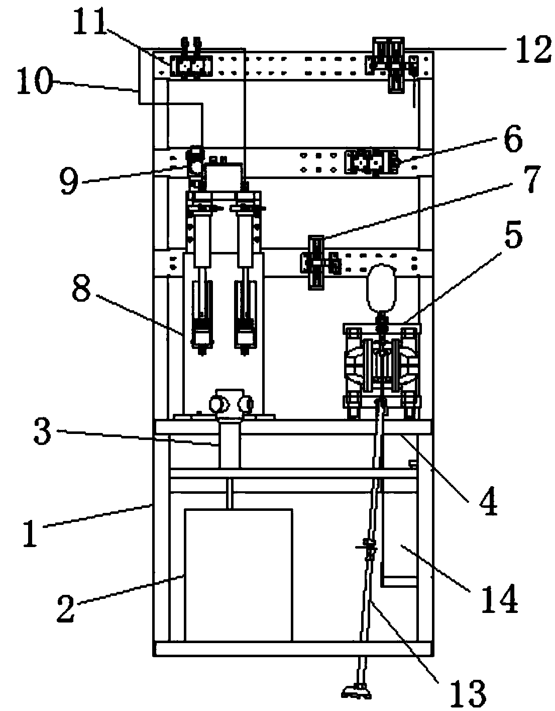
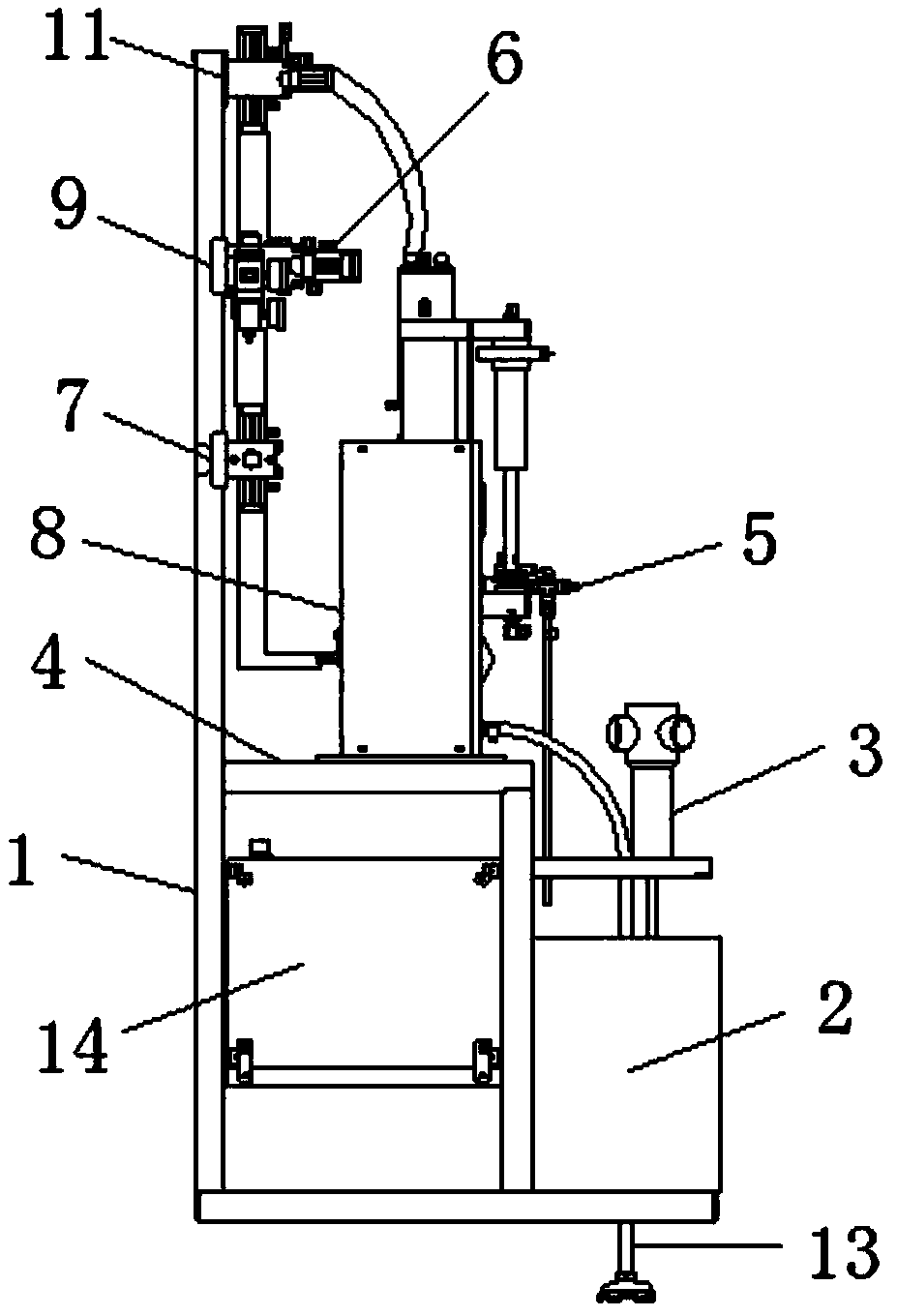
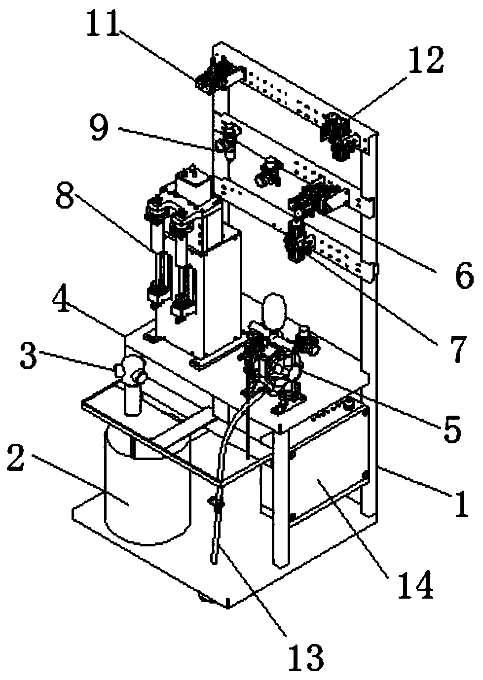
[0024] Such as Figure 1-3 As shown, an injection paint supply system includes a frame 1, a paint bucket 2 and a partition 4, the paint bucket 2 is placed on one side of the frame 1, and the partition 4 is fixedly welded on one side of the frame 1 wall, one side of the partition 4 is fixedly connected with an agitator 3, and the output end of the agitator 3 is located in the inner cavity of the paint bucket 2, the surface of the partition 4 is fixed with a diaphragm pump 5 through a screw, and the top of the diaphragm pump 5 is A paint color change valve 6 is fixedly installed on the surface of the frame 1, a feed distribution valve 7 is fixed on one side of the paint color change valve 6, and a paint injection valve 8 is fixed on the surface of the partition 4 on one side of the diaphragm pump 5, The top of the paint injection valve 8 is located on the surface of the frame 1, and an air source decompression filter 9 is fixedly installed. One side of the air source decompressi...


PUM


Abstract

The invention discloses an injection-type paint supply system. The injection-type paint supply system comprises a rack, a coating barrel and a partition, wherein the coating barrel is placed on one side of the rack; the partition is fixedly welded on a side wall of the rack; a stirrer is fixedly connected to one side of the partition; an output end of the stirrer is located in the inner chamber ofthe coating barrel; a diaphragm pump is fixed on the surface of the partition through a screw; and a coating color change valve is fixedly mounted in the position, on the surface of the rack, at thetop of the diaphragm pump. The injection-type paint supply system is reasonable and novel in design and convenient to mount and operate; during later use, the rotational speed of a motor and the flowrate of a coating are in a linear corresponding relationship; the flow rate accuracy of a liquid is high; numerical control can be realized; the response to a control signal is quick; the flow rate can be changed in real time; quick cleaning and color change can be realized; when a robot is used together, automatic batch production of various small-batch products can be realized; and the injection-type paint supply system integrates environmental friendliness and high efficiency, has high practicability and is suitable for popularization.

Description

technical field [0001] The invention relates to a paint supply system, in particular to an injection paint supply system. Background technique [0002] Spraying is a coating method in which paint is dispersed into uniform and fine droplets by means of pressure or centrifugal force through a spray gun or a disc atomizer, and then applied to the surface of the object to be coated. Among them, the spraying operation can be divided into air spraying, airless spraying, electrostatic spraying and various derivations of the above basic spraying forms, such as large flow and low pressure atomization spraying, thermal spraying, automatic spraying, multi-group spraying, etc. [0003] In the process of spraying the surface of the product through spraying equipment, the paint supply system is an important part of the spraying equipment. Among them, for the paint supply system adopted by the existing spraying equipment, in the actual use process, there are generally defects that it is i...

Claims


Application Information

Patent Timeline
Patent Type & Authority Applications(China)
IPC IPC(8): B05B9/04B05B15/20B05B12/08B05B12/14B05B15/555
CPCB05B9/0413B05B12/085B05B12/149B05B15/20B05B15/555
Inventor 陆勇
Owner 东莞市瀚晟自动化设备有限公司
Why Eureka
Try Eureka