Conductive and reflective layer and application thereof in electrochromic device
An electrochromic device, conductive reflection technology, applied in instruments, optical components, optics, etc., can solve the problem of high light loss value
- Summary
- Abstract
- Description
- Claims
- Application Information
AI Technical Summary
Problems solved by technology
Method used
Image

Examples
Embodiment 1
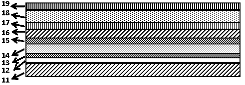
[0047] according to figure 1 The structure shown is magnetron sputtering (metal niobium target, purity 99.9%, oxygen-argon mixed atmosphere, sputtering pressure 0.2Pa, oxygen-argon partial pressure ratio 4 / 6, sputtering power 4KW, sputtering time 20min) on the glass substrate 11 to deposit a layer of niobium pentoxide layer 12 with a thickness of 400 nm; using metallic silver as the target material, through magnetron sputtering (silver target, purity 99.99%; sputtering conditions: background Vacuum is 1×10 -3 Pa, the working pressure is 0.3Pa, the power is 16W, and the time is 5min) deposit a layer of silver reflective layer 13 with a thickness of 10 nm on the niobium pentoxide layer; by (1-x)ZnO+xAl 2 o 3 (x = 2 wt%) sintered ceramics as the target, by radio frequency magnetron sputtering (room temperature, oxygen and argon mixed atmosphere, sputtering pressure is 0.5Pa, oxygen partial pressure is 1×10 -2 Pa, the power is 100W, and the time is 30min), a layer of aluminum-d...
Embodiment 2
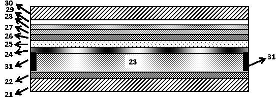
[0049] according to figure 2 The structure shown is made of 10 wt% SnO 2 and 90 wt%In 2 o 3 The sintered ceramics are used as the target material, and the radio frequency magnetron sputtering method (room temperature, oxygen and argon mixed atmosphere, sputtering pressure is 0.5Pa, oxygen partial pressure is 1×10 -2 Pa, the power is 100W, and the time is 30 minutes) on the first glass substrate 21, a conductive layer of indium tin oxide 22 with a thickness of 150 nm is plated.
[0050] by (1-x)ZnO+xAl 2 o 3 (x = 2 wt%) sintered ceramics as the target, by radio frequency magnetron sputtering (room temperature, oxygen and argon mixed atmosphere, sputtering pressure is 0.5Pa, oxygen partial pressure is 1×10 -2 Pa, the power is 100W, and the time is 40 minutes) on the second glass substrate 30, a layer of aluminum-doped zinc oxide layer 29 with a thickness of 200 nm is coated. Using metal gold as the target material, through radio frequency magnetron sputtering (gold target...
PUM
| Property | Measurement | Unit |
|---|---|---|
| thickness | aaaaa | aaaaa |
| thickness | aaaaa | aaaaa |
| thickness | aaaaa | aaaaa |
Abstract
Description
Claims
Application Information
 - R&D
- Intellectual Property
- Life Sciences
- Materials
- Tech Scout
- Unparalleled Data Quality
- Higher Quality Content
- 60% Fewer Hallucinations
Browse by: Latest US Patents, China's latest patents, Technical Efficacy Thesaurus, Application Domain, Technology Topic, Popular Technical Reports.
© 2025 PatSnap. All rights reserved.Legal|Privacy policy|Modern Slavery Act Transparency Statement|Sitemap|About US| Contact US: help@patsnap.com