
Power transmission system, wind power generator set and wind power plant

A technology for wind turbines and power transmission, applied in power transmission AC networks, wind power generation, electrical components, etc., can solve the problems of low line utilization, increased system cost, and high loss and loss, so as to increase power transmission distance, improve Line utilization, skin effect avoidance effect

Pending Publication Date: 2018-09-07
BEIJING GOLDWIND SCI & CREATION WINDPOWER EQUIP CO LTD
View PDF9 Cites 6 Cited by
  • Summary
  • Abstract
  • Description
  • Claims
  • Application Information

AI Technical Summary

Problems solved by technology

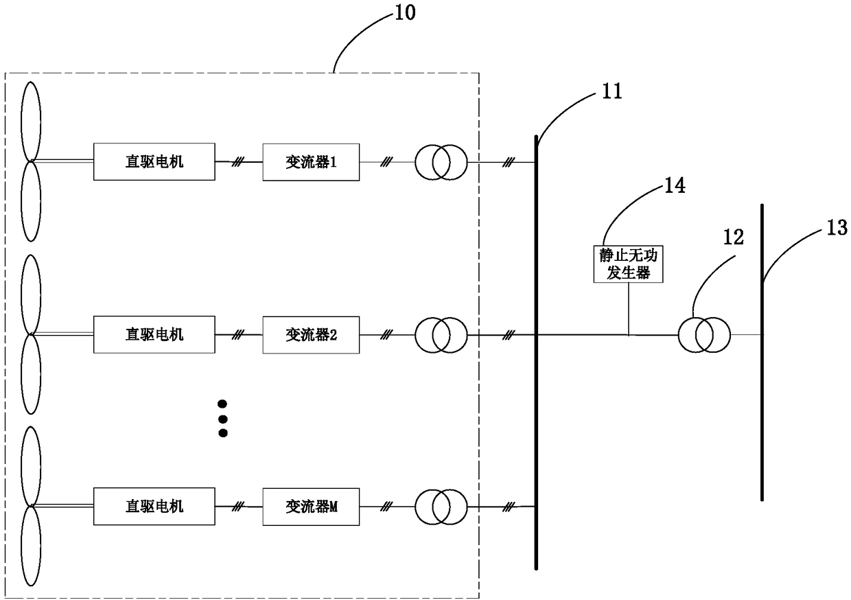
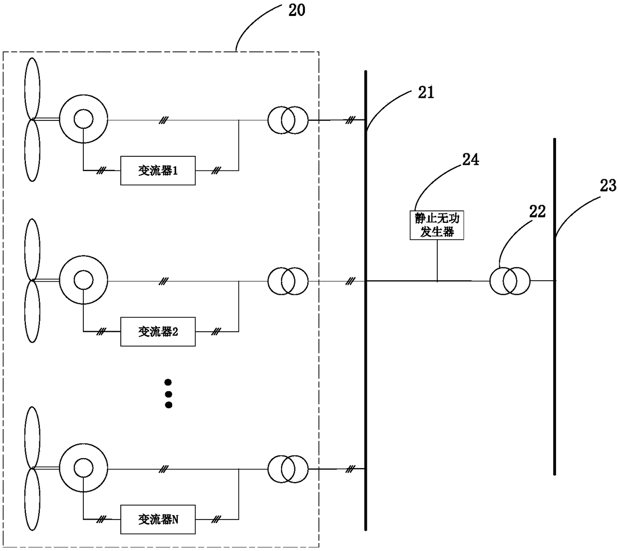
This method not only has high line cost, poor economy, and short transmission distance; but also when AC power is transmitted, there is a skin effect in the line, which leads to low line utilization and high loss; in addition, when the AC power is transmitted, the wind speed Changes will cause grid voltage fluctuations; at the same time, SVG needs to be added to the circuit system for reactive power compensation, which increases system costs and losses

Method used


Image

  • Power transmission system, wind power generator set and wind power plant
  • Power transmission system, wind power generator set and wind power plant
  • Power transmission system, wind power generator set and wind power plant

Examples


Embodiment Construction

[0034] Features and exemplary embodiments of various aspects of the invention will be described in detail below. In the following detailed description, numerous specific details are set forth in order to provide a thorough understanding of the present invention. It will be apparent, however, to one skilled in the art that the present invention may be practiced without some of these specific details. The following description of the embodiments is only to provide a better understanding of the present invention by showing examples of the present invention. The present invention is by no means limited to any specific configurations and algorithms presented below, but covers any modification, substitution and improvement of elements, components and algorithms without departing from the spirit of the invention. In the drawings and the following description, well-known structures and techniques have not been shown in order to avoid unnecessarily obscuring the present invention.

...


PUM


Abstract

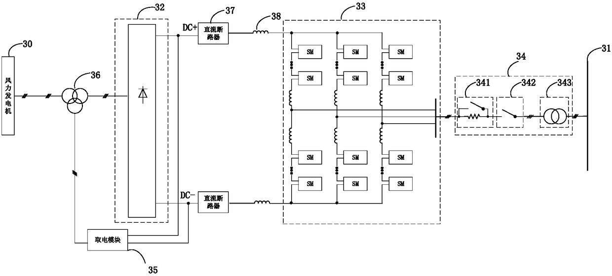
The invention discloses a power transmission system, a wind power generator set and a wind power plant, which are used for transmitting power in a direct current form, reducing construction cost of apower transmission line and line loss during the power transmission process, improving line utilization ratio, extending power transmission distance and simultaneously preventing a skin effect in theline. The power transmission system is used for transmitting electric energy generated by the wind power generator set to a power grid and comprises a machine-side rectification module, grid-side inversion module, a grid-connected module and a power taking module, wherein the machine side rectification module is used for connecting the wind power generator set, the machine-side rectification module, the grid-side inversion module and the grid-connected module are sequentially connected, the grid-connected module is used for connecting the power grid, an input end of the power taking module isconnected with the grid side inversion module, and an output end of the power taking module is used for connecting the wind power generator set.

Description

technical field [0001] The invention relates to the technical field of power electronics, in particular to an electronic transmission system, a wind power generating set and a wind farm. Background technique [0002] The electric energy generated by the wind turbine needs to be connected to the grid for transmission. When the electricity generated by the wind turbine is connected to the grid, the traditional power transmission scheme is a direct-drive AC transmission system or a doubly-fed AC transmission system. [0003] Such as figure 1 as shown, figure 1 The circuit topology of the direct drive AC transmission system is shown in . In the wind farm 10, after the electric energy generated by each direct drive motor is converted by the converter, the 690-volt low-voltage alternating current is converted into a 35-kilovolt (KV) medium-voltage alternating current through the booster, and then imported into the central The 35KV medium-voltage alternating current in the high-...

Claims


Application Information

Patent Timeline
Patent Type & Authority Applications(China)
IPC IPC(8): H02J3/36H02J3/38
CPCH02J3/386H02J3/36Y02E60/60Y02E10/76
Inventor 李战龙刘世军杨有涛
Owner BEIJING GOLDWIND SCI & CREATION WINDPOWER EQUIP CO LTD
Learn More