Supercharge Your Innovation With Domain-Expert AI Agents!

A Cylindrical Transverse Flux Switched Reluctance Linear Motor with Modular Stator

A technology of transverse magnetic flux and linear motors, which is applied in the direction of electromechanical devices, electrical components, electric components, etc., can solve the problems of increasing the eddy current loss of the motor, the average output of the motor is not high, and reducing the volume ratio of the motor output, so as to reduce the eddy current loss , Ease of production and assembly

Active Publication Date: 2021-02-09
CHINA UNIV OF MINING & TECH
View PDF5 Cites 0 Cited by
  • Summary
  • Abstract
  • Description
  • Claims
  • Application Information

AI Technical Summary

Problems solved by technology

In the traditional longitudinal flux cylindrical switched reluctance linear motor, because part of the magnetic flux direction is parallel to the motor shaft, the eddy current loss of the motor is increased. In addition, due to the large magnetic flux leakage in the stator mover slot, the electromagnetic output of the motor is less saturated. Faster, reducing the output volume ratio of the motor
However, the existing transverse flux cylindrical switched reluctance linear motor lacks the optimization of the relationship between the effective magnetic circuit and the average output force and the output pulsation, so the average output force of the motor may not be high and the output pulsation may be large

Method used


Image

  • A Cylindrical Transverse Flux Switched Reluctance Linear Motor with Modular Stator
  • A Cylindrical Transverse Flux Switched Reluctance Linear Motor with Modular Stator
  • A Cylindrical Transverse Flux Switched Reluctance Linear Motor with Modular Stator

Examples


Embodiment Construction

[0013] An embodiment of the present invention will be further described below in conjunction with accompanying drawing:

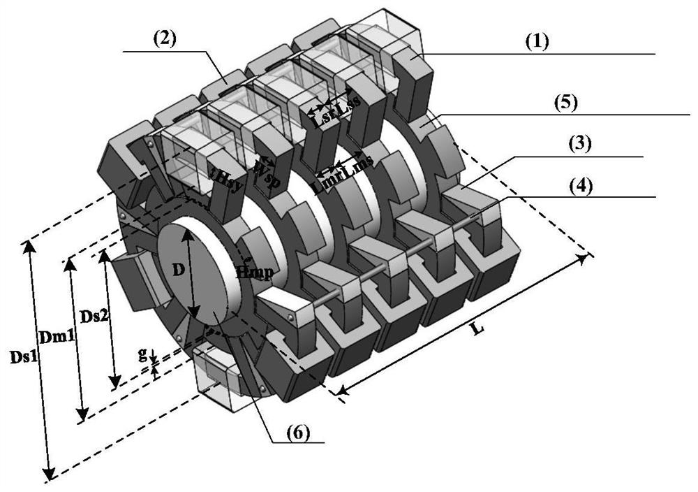
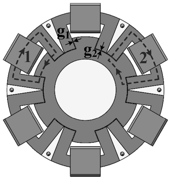
[0014] The single-phase cylindrical transverse flux switch reluctance linear motor of this embodiment consists of a U-shaped modular stator (1), a stator winding (2), a stator gasket (3), a gasket fixing screw (4), a mover Composed of a ferromagnetic ring (5) and a mover shaft (6). The modular stator and the stator gasket are placed alternately on the cross-section, the ferromagnetic ring of the mover is sleeved on the mover shaft, and the salient poles on the mover ring are buckled at the opening of the U-shaped modular stator (1); in the circumferential direction The winding direction of the two adjacent stator windings is opposite; all the windings in the longitudinal direction have the same winding direction; there are 6 windings in the circumferential direction; the angle between the two adjacent windings is staggered by 60°.

[0015] In this embodime...


PUM


Abstract

The invention discloses a novel cylindrical transverse flux switch reluctance linear motor with a modular stator and belongs to the field of new motor design. Compared with the conventional longitudinal flux switch reluctance linear motor, the novel cylindrical transverse flux switch reluctance linear motor with the modular stator in the invention can better form an effective magnetic circuit andhas smaller output pulsation. The novel cylindrical transverse flux switch reluctance linear motor in the invention consists of a U-shaped modular stator, a stator winding, a stator spacer, a spacer fixing screw, a rotor ferromagnetic ring and a rotor shaft, wherein the modular stator and the stator spacer are placed in sequence on the cross section; the rotor ferromagnetic ring is sleeved on therotor shaft, and a salient pole on the rotor ring is fastened at the opening of the U-shaped modular stator; two adjacent stator windings in the peripheral direction are wound in an opposite direction; all windings in the longitudinal direction are wound in the same direction; and all the windings are connected in series to ensure simultaneous energization. The magnetic flux of the motor of the invention is a transverse magnetic flux, the stator part is a modular stator, which brings convenience for production and assembly; meanwhile, the motor has the advantages of large average output, smalloutput pulsation, simple structure, easiness for maintenance, high reliability and the like.

Description

technical field [0001] The invention relates to the field of motor design, in particular to a switched reluctance linear motor. Background technique [0002] In recent years, linear motors have been more and more used in rail transit, magnetic levitation systems, aviation systems, military industries and other fields. Among them, the switched reluctance linear motor has become a research hotspot in recent years due to its strong structure, high reliability, good fault tolerance, no permanent magnet material, and stator concentrated winding. The large normal force caused by the inherent structural defects of the traditional unilateral switched reluctance linear motor often causes a large friction force between the mover and the track, which will affect the service life of the motor. The double-sided switched reluctance linear motor can reduce the normal force by virtue of its double-sided stator structure, but as long as there is an irregular double-sided air gap caused by t...

Claims


Application Information

Patent Timeline
Patent Type & Authority Patents(China)
IPC IPC(8): H02K41/03H02K3/28
CPCH02K3/28H02K41/03H02K2213/12
Inventor 陈昊聂瑞赵枢棪
Owner CHINA UNIV OF MINING & TECH
Features
  • R&D
  • Intellectual Property
  • Life Sciences
  • Materials
  • Tech Scout
  • Unparalleled Data Quality
  • Higher Quality Content
  • 60% Fewer Hallucinations
Learn More