Eureka AIR delivers breakthrough ideas for toughest innovation challenges, trusted by R&D personnel around the world.

Optical fiber line loss and optical fiber end surface loss detection system

A technology of optical fiber line and optical fiber end face, which is applied in the field of optical fiber line loss and optical fiber end face loss detection system, can solve the problems of poor quality of optical fiber network construction, difficult use, high price, etc. The effect of engineering construction and supervision and reducing equipment input cost

Pending Publication Date: 2018-09-07
NANJING XIUDEA COMM TECH CO LTD
View PDF6 Cites 14 Cited by
  • Summary
  • Abstract
  • Description
  • Claims
  • Application Information

AI Technical Summary

Problems solved by technology

[0002] At present, optical fiber communication has achieved large-scale coverage, especially the popularization of FTTH fiber-to-the-home. People's dependence on the network is increasing day by day. However, the supervision of optical fiber network construction is not in place, resulting in poor quality of optical fiber network construction. The acceptance of construction projects can only be opened or not. It is impossible to accurately judge the loss and cracking of each segment of fiber and each node in the fiber optic line, which seriously affects the user's experience of the fiber optic network. Operators need to spend more money on network maintenance. Users also have to bear the economic losses caused by disconnection
[0003] The products currently available on the market to detect fiber line loss and fiber end face loss are optical time domain reflectometers, which use the reflection loss phenomenon of light waves at the fiber loss point and the coupling point of the fiber connector to launch the detection light wave in the fiber line , by detecting the light wave returned from the original path, the distance between the loss point and the coupling point and the reflected light wave intensity at this point are measured, so as to indirectly judge the connection loss and the total line loss of the loss point and the coupling point. The loss point and coupling point on the line, and the optical fiber line are tested in high speed and in batches, and the fault point can be accurately located. However, due to the high price of the equipment, the price exceeds tens of thousands of yuan, and it cannot be equipped in large quantities to ordinary construction personnel. The difficulty has brought about the fact that this equipment is rarely used in engineering construction. The key is that it is impossible to upload the test data and on-site port number information to the cloud server to form a complete optical fiber line routing topology map and provide operators with optical fiber node loss and loss information. Complete information such as the amount of change, which is also the main problem to be solved by the patent of the present invention

Method used

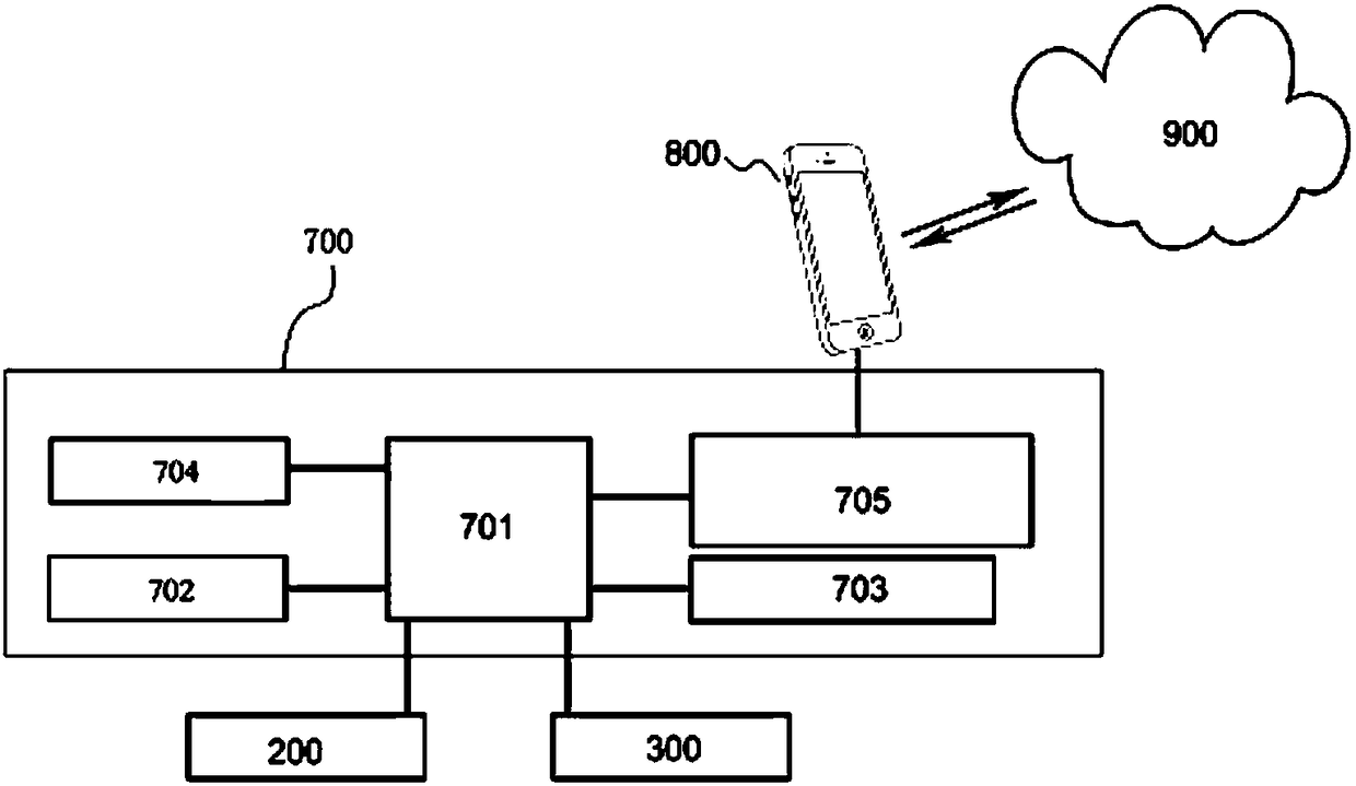
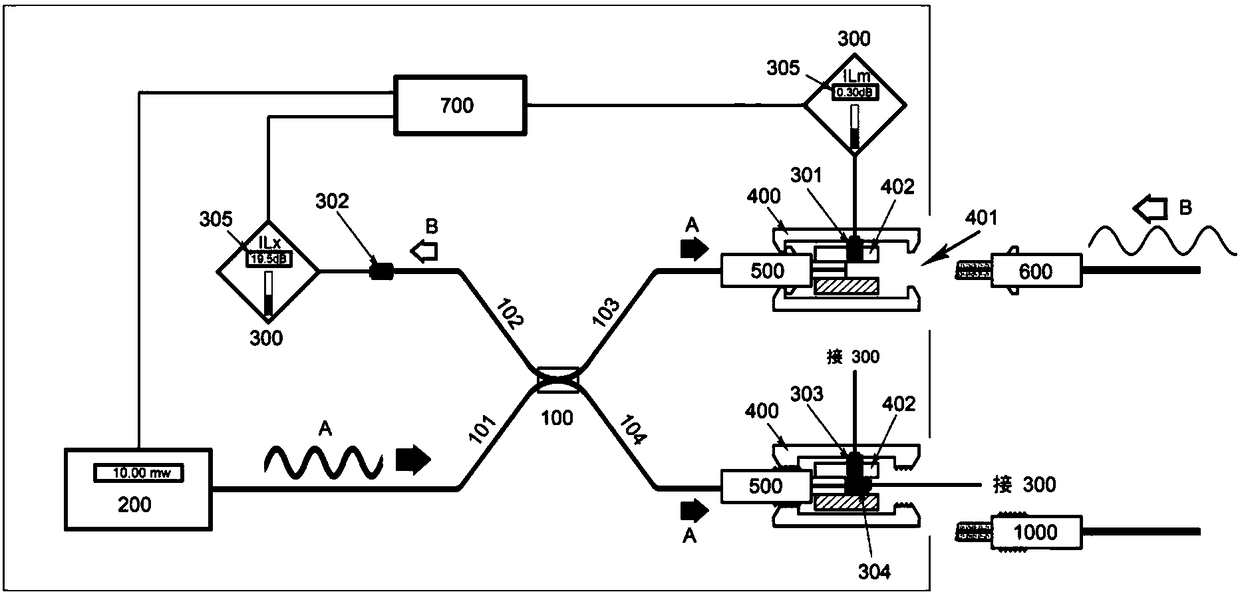
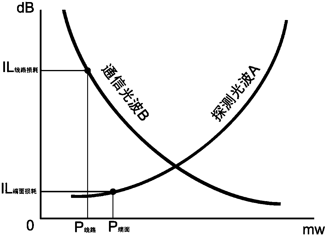

Image

  • Optical fiber line loss and optical fiber end surface loss detection system
  • Optical fiber line loss and optical fiber end surface loss detection system
  • Optical fiber line loss and optical fiber end surface loss detection system

Examples


Embodiment Construction

[0024] In order to make the above objects, features and advantages of the present invention more obvious and comprehensible, specific implementations of the present invention will be described in detail below in conjunction with the accompanying drawings.

[0025] In the following description, a lot of specific details are set forth in order to fully understand the present invention, but the present invention can also be implemented in other ways different from those described here, and those skilled in the art can do it without departing from the meaning of the present invention. By analogy, the present invention is therefore not limited to the specific examples disclosed below.

[0026] Second, "one embodiment" or "an embodiment" referred to herein refers to a specific feature, structure or characteristic that may be included in at least one implementation of the present invention. "In one embodiment" appearing in different places in this specification does not all refer to ...


PUM


Abstract

The invention discloses an optical fiber line loss and optical fiber end surface loss detection system. According to the detection system, a stabilized light source, a positive detector of an opticalpower meter and a detection end standard connector are connected together through a light splitter; the positive detector of the optical power meter is used for detecting communication optical waves,and a side detector detects the loss of the end surface of the optical fiber; a control part uploads test data to a cloud server through a terminal; meanwhile, the terminal uploads the collected optical fiber port, the equipment code, the construction site information, the construction personnel information, and the address information to the cloud server; the cloud server analyzes and processes the received information to form a topological graph of the optical fiber line port and a loss and coding information table; a construction work order and a route searching instruction can also be downloaded, so as to guide the engineering construction personnel to complete the construction and maintenance of the optical fiber lines; and meanwhile engineering construction and supervision are facilitated.

Description

technical field [0001] The invention relates to the field of optical fiber line loss and optical fiber connector termination quality detection. The system connects a stable light source, a forward detector of an optical power meter, and a standard connector of a detection end through an optical splitter, and the forward detection of the optical power meter The detector detects the communication light wave, the side detector detects the loss of the fiber end face, the control part uploads the test data to the cloud server through the terminal, and at the same time, the terminal collects the collected fiber port, equipment code, construction site information, construction personnel information, and address information together. Upload to the cloud server, and the cloud server will analyze and process the received information to form a topology map of the optical fiber line port and a table of loss and coding information, and can also download construction work orders and routing ...

Claims


Application Information

Patent Timeline
Patent Type & Authority Applications(China)
IPC IPC(8): H04B10/079H04L29/08H04M1/725
CPCH04B10/0795H04B10/07955H04L67/12H04M1/72403
Inventor 吕根良
Owner NANJING XIUDEA COMM TECH CO LTD
Why Eureka
Eureka Blog
Learn More