Battery spot welding device

A spot welding device and battery technology, applied in auxiliary devices, welding equipment, auxiliary welding equipment, etc., can solve the problems of insecurity, low welding efficiency of manual hand-held cells and protective plates, etc., and achieve high safety, high efficiency, Avoid the effect of getting too close

Pending Publication Date: 2018-09-11
贵州鸿兴时代动力新能源科技有限公司
View PDF7 Cites 3 Cited by
  • Summary
  • Abstract
  • Description
  • Claims
  • Application Information

AI Technical Summary

Problems solved by technology

[0003] The invention discloses a battery electric welding device, aiming at solving the problem of low efficien

Method used


Image

  • Battery spot welding device
  • Battery spot welding device
  • Battery spot welding device

Examples


Embodiment Construction

[0016] The following is further described in detail through specific implementation methods:

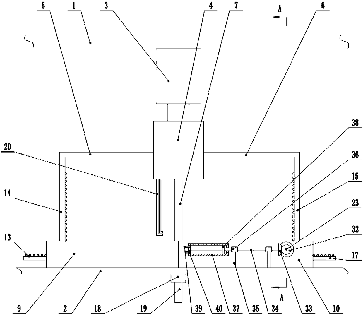
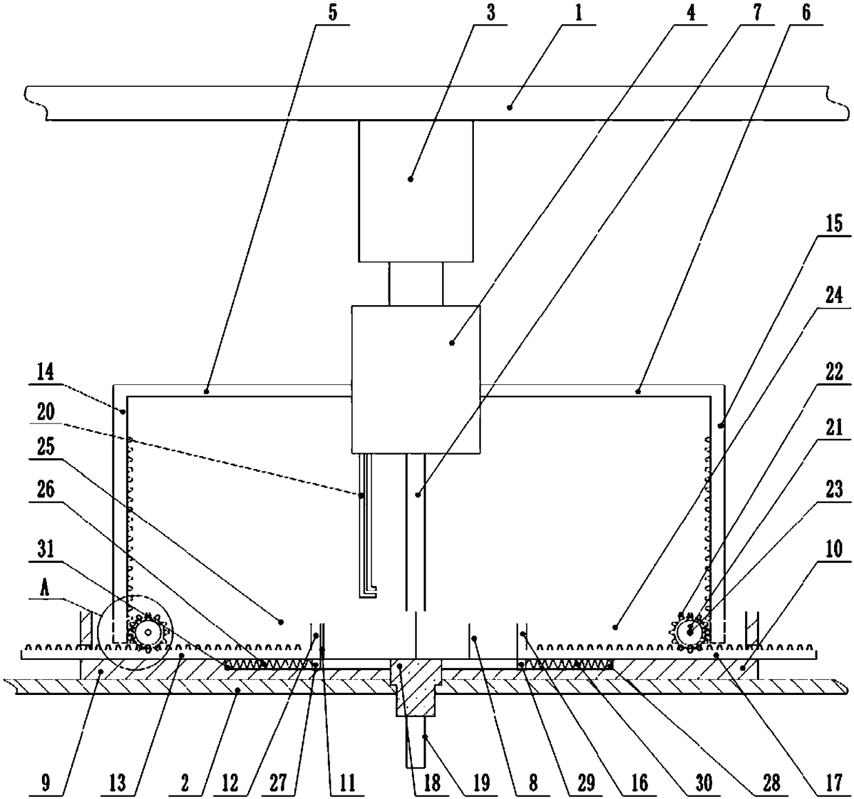
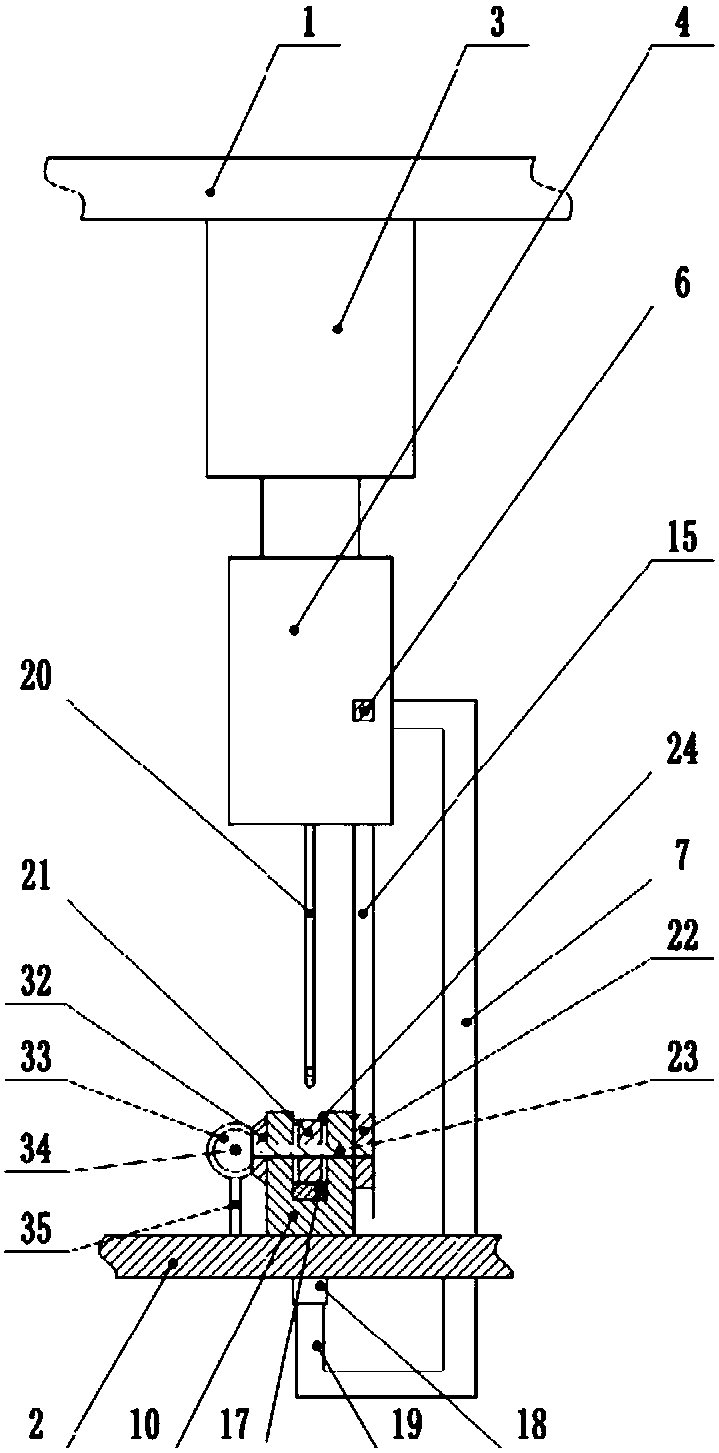
[0017] The reference signs in the drawings of the specification include: frame 1, workbench 2, hydraulic cylinder 3, spot welding machine 4, left connecting rod 5, right connecting rod 6, connecting frame 7, electric core 8, protection plate feed rail 9. Battery feed rail 10, protection plate 11, left push plate 12, left rack 13, left drive rack 14, right drive rack 15, right push plate 16, right rack 17, workpiece ejection Block 18, workpiece ejection rod 19, spot welding pin 20, right driven gear 21, right driving gear 22, right rotating shaft 23, right groove 24, left groove 25, left reset extension spring 26, left bump 27, Right limit groove 28, right bump 29, right reset extension spring 30, left limit groove 31, first bevel gear 32, second bevel gear 33, lead screw 34, support column 35, bearing 36, cylinder barrel 37, Piston plate 38, liquid outlet pipe 39, liquid inlet pipe ...


PUM


Abstract

The invention belongs to the technical field of coating or plating equipment by means of brazing or welding methods, and in particular discloses a battery spot welding device. The battery spot weldingdevice comprises a rack and a worktable, wherein the worktable is located below the rack; a hydraulic cylinder is fixedly mounted on the rack; the output end of the hydraulic cylinder is fixedly connected to a spot-welder; a spot-welding needle is fixedly mounted on the lower end surface of the spot-welder; a part feeding mechanism is fixedly mounted on the upper end surface of the worktable; thepart feeding mechanism is used for driving a protecting plate and a battery cell to move in opposite directions till the protecting plate and the battery cell are laminated; the part feeding mechanism is driven by the spot-welder; a glue spraying mechanism is arranged in the part feeding mechanism for spraying glue to the battery cell; and the glue spraying mechanism is driven by the part feedingmechanism. The battery spot welding device aims to solve the problems that the efficiency is low and the safety cannot be ensured as the battery cell and the protecting plate are manually held to weld in the prior art.

Description

technical field [0001] The invention belongs to the technical field of cladding or plating equipment by means of brazing or welding, and specifically discloses a battery spot welding device. Background technique [0002] In the production process of lithium batteries, after the battery cell is manufactured, the protective plate needs to be installed on the battery cell. At present, the protective plate is usually fixedly connected to the battery cell by spot welding, but in the spot welding process of the protective plate, Workers need to hold the battery cell in one hand and the protective plate in the other, and then weld with an electric spot welder, which has the problem of low welding efficiency. At the same time, the high temperature and current generated during welding pose a threat to the life safety of workers. Contents of the invention [0003] The invention discloses a battery electric welding device, aiming to solve the problem of low efficiency and unsafety in...

Claims


Application Information

Patent Timeline
IPC IPC(8): B23K37/00B23K37/04
CPCB23K37/00B23K37/0426
Inventor 金璇陈兴奎黎标
Owner 贵州鸿兴时代动力新能源科技有限公司
Why Eureka
Try Eureka