Device for plate machining

A plate processing and sliding plate technology, applied in the field of material processing, can solve problems such as excessive movement and insufficient movement

Active Publication Date: 2018-09-11
重庆市永川区豪安星木材有限责任公司
View PDF6 Cites 0 Cited by
  • Summary
  • Abstract
  • Description
  • Claims
  • Application Information

AI Technical Summary

Problems solved by technology

[0004] The purpose of the present invention is to provide a device for plate processing, which solves the problem of excessive movement or insufficient movement in the prior art when moving the cutting knife

Method used


Image

  • Device for plate machining
  • Device for plate machining
  • Device for plate machining

Examples


Embodiment Construction

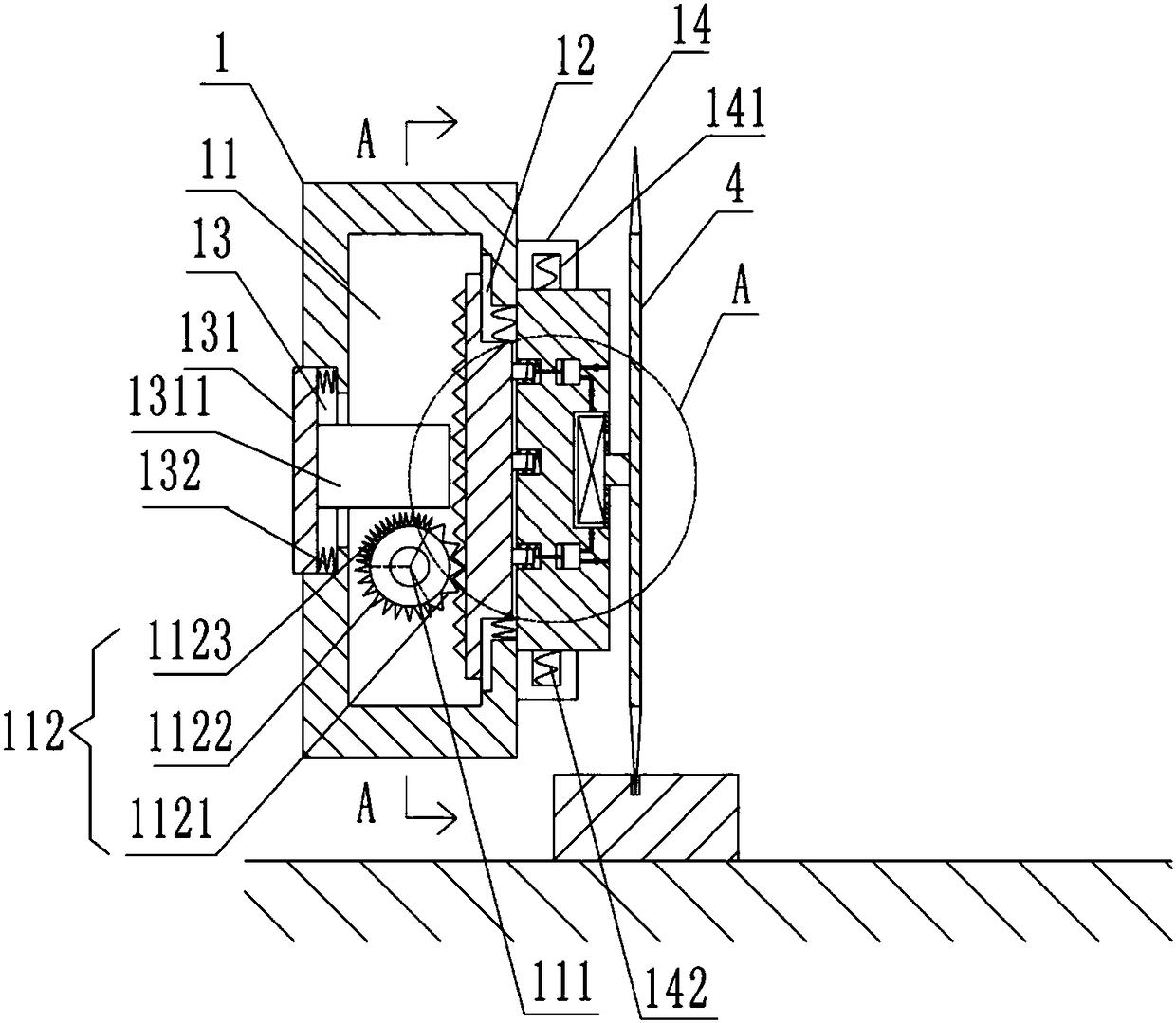
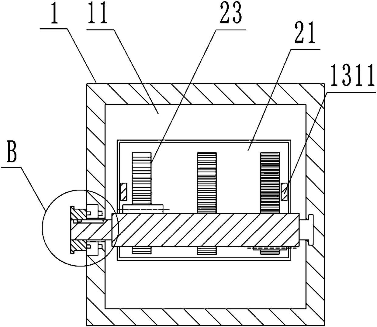
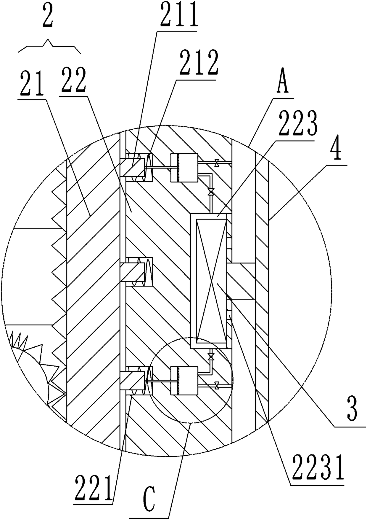
[0026] The present invention will be described in further detail below by means of specific embodiments:

[0027] The reference signs in the accompanying drawings of the description include: fixed seat body 1, cavity 11, rotating shaft 111, arc-shaped rack 112, large-scale adjustment rack 1121, small-range adjustment rack 1122, fine-tuning rack 1123, bar-shaped mouth 12. Button cavity 13, button plate 131, button rod 1311, button spring 132, slide bar 14, chute 141, return spring 142, slide plate 2, first plate 21, ejector rod 211, ejector rod spring 212, second Plate 22, linear rack 23, pressing chamber 221, inflating part 222, air cylinder 2221, piston 2222, piston rod 2223, air blowing pipe 2224, air intake pipe 2225, motor cavity 223, cooling channel 2231, motor 3, cutter 4, handle 5. Hand-held plate 51, sliding protrusion 511, positioning protrusion 512, connecting rod 52, strip chute 521, positioning cavity 6, groove 61, wedge-shaped block 62.

[0028] In order to achie...


PUM


Abstract

The invention relates to the technical field of material processing, in particular to a device for plate machining. The device for plate machining comprises a fixing base, a sliding plate and a cutting tool, wherein the cutting tool is driven by a motor. A cavity is formed in the fixing base, and a rotating shaft which is connected with the cavity wall of the cavity in a rotating mode is arrangedin the cavity. One end of the rotating shaft stretches out of the fixing base and is fixedly provided with a handle. A locating portion is arranged on the outer wall of the fixing base, and arc-shapedracks are arranged on the surface of the portion, located in the cavity, of the rotating shaft. The sliding plate comprises a first plate, a second plate and linear racks, wherein the linear racks mesh with the corresponding arc-shaped racks. The first plate is connected with the fixing base in a sliding mode. The second plate is connected with the fixing base in a sliding mode, and press cavities, an air pumping portion and a motor cavity are arranged in the second plate. A button cavity is formed in the surface of the fixing base, a button plate is arranged in the button cavity, and buttonrods are fixed to the button plate. Ejector rods are further arranged on the first plate, and ejector rod springs are arranged between the ejector rods and the cavity walls of the press cavities. By the adoption of the scheme, the problem that in the prior art, when the cutting tool is moved, the phenomenon of excessive movement or uncompleted movement is prone to happening is solved.

Description

technical field [0001] The invention relates to the technical field of material processing, in particular to a device for plate processing. Background technique [0002] Furniture includes home furniture and school furniture, where school furniture includes desks, dormitory beds, wardrobes, and the like. The production process of general school furniture is: material selection-cutting-drying treatment-fine carving-insecticidal treatment-polishing-painting-assembly. Wherein, in the process of cutting boards (such as wood boards), the processing of the tenon and groove is generally involved. In the prior art, when the tenon and groove is processed on wood, it is generally formed by cutting with a special machine. [0003] The existing technology has the following technical problems: when the existing technology is processing the tenon and groove on the plate, the depth of the tenon and groove is not the same; when the existing machine processes the tenon and groove with diffe...

Claims


Application Information

Patent Timeline
Patent Type & Authority Applications(China)
IPC IPC(8): B27F5/02B27G21/00
CPCB27F5/02B27G21/00
Inventor 刘成华
Owner 重庆市永川区豪安星木材有限责任公司
Why Eureka
Try Eureka