
Deburring device for TB tyre side surface

A deburring and tire technology, applied in the field of tire manufacturing, can solve the problems of substandard trimming quality, unevenness, and irregular tire side curve, so as to improve the trimming quality, ensure the removal effect, and improve the trimming efficiency.

Active Publication Date: 2018-09-11
JIANGSU UNIV
View PDF7 Cites 14 Cited by
  • Summary
  • Abstract
  • Description
  • Claims
  • Application Information

AI Technical Summary

Problems solved by technology

Analysis of its causes: 1) The side curve of the tire is irregular; 2) There are various specification information printed on the side of the tire, which is uneven; 3) It is difficult for the trimming tool to fit tightly with the tread; 4) The tool is on the tread It is difficult to control the pressure evenly
Based on the above objective conditions of the side shape of the tire, it is difficult to ensure the uniformity of the burr removal by the blade, resulting in substandard trimming quality

Method used


Image

  • Deburring device for TB tyre side surface
  • Deburring device for TB tyre side surface
  • Deburring device for TB tyre side surface

Examples


Embodiment Construction

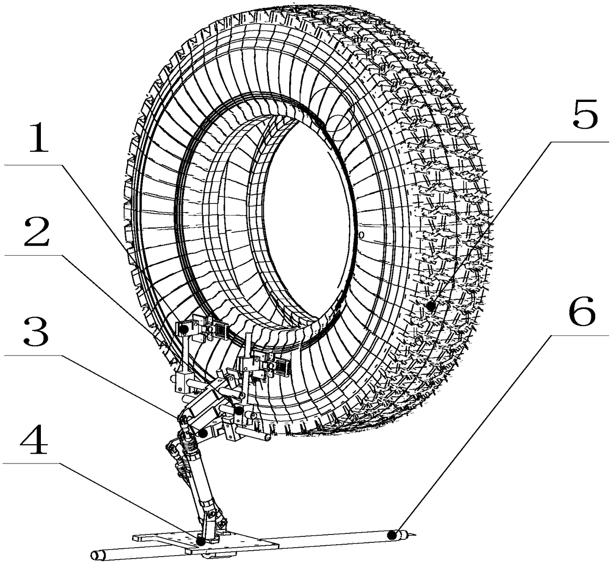
[0024] figure 1 For a complete schematic diagram of the TB tire side deburring device, the trimming tool mechanisms 1, 2, and 3 are all installed on the frame translation assembly 4, and placed on both sides of the tire 5 (the tire 5 is positioned by the clamping and rotating device and It can be driven by the ball screw on the frame translation component 4 to move along the ball screw guide rail, and each trimming tool is spaced at a certain distance in the horizontal and vertical directions, which can prevent the tool and the mechanism. Interference and collision occur between them and affect the operation of the machine.

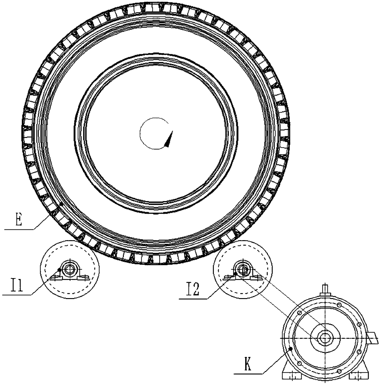
[0025] figure 2 It is a schematic diagram of a tire clamping and rotating device, wherein the tire clamping and rotating device is composed of rollers I1 and I2, a driving motor K, a pulley, and a belt. The drive motor K is connected with the first pulley through a key, the roller I2 (drive roller) is connected with the first pulley through a key, and ...


PUM

PropertyMeasurementUnit
radiusaaaaaaaaaa

Abstract

The invention relates to the field of tyre manufacture and particularly relates to a deburring device for a TB tyre side surface. The device includes two sets of cutting tool assemblies that are symmetrical left and right, a rack translation assembly, a tyre and a ball screw. The two sets of cutting tool assemblies are installed on the rack translation assembly and are disposed at both sides of the tyre; opening and closing motion driven by the ball screw is performed on the rack translation assembly to control the distance from the tyre side surface; the tyre is driven by a clamping rotationdevice to perform uniform speed rotary motion, and when the motion is smooth, the cutting tool assemblies are driven by the ball screw to move the tire at a uniform speed on the rack translation assembly, and stop when the cutting tool assemblies move to a suitable distance; at this time, cylinders of cutting tool mechanisms in the cutting tool assemblies perform air inlet work, and cutting toolsare pushed out on a to-be-trimmed tire, and then the cutting assemblies move downward as a whole, and when cutting blades complete trimming deflashing on a tyre surface, the cylinders work at this time, and the cutting tools are recovered; and the cutting tool assemblies are driven by the ball screw to move away from the tyre at the uniform speed until an entire trimming deflashing process is completed.

Description

technical field [0001] The invention relates to the field of tire manufacturing, in particular to a device for deburring the side of a TB tire. Background technique [0002] With the growth of automobile production, the demand for tires is also increasing. However, due to the limitation of the tire production process, lanugo will be produced on the tread and sidewall of the tire. The lanugo will not only affect the appearance, increase the friction between the tire and the ground, but also generate noise when the car is running at high speed, so it should be removed. When using the traditional manual tire trimming machine, there are many manual operations, high labor intensity, low production efficiency, unstable and uneven product quality, and also affects the health of the operators. The automatic tire trimming machine has its outstanding advantages over the traditional trimming machine, but there are also some problems. At present, there are already automatic tire trimm...

Claims


Application Information

Patent Timeline
Patent Type & Authority Applications(China)
IPC IPC(8): B29C37/02B29L30/00
CPCB29C37/02B29L2030/002B29L2030/007
Inventor 杨超君鲁建武
Owner JIANGSU UNIV
Learn More