Chemiluminescence micro-fluidic chip and analytical instrument containing chemiluminescence micro-fluidic chip

A microfluidic chip and chemiluminescent technology, applied in the field of microelectronics, can solve problems such as unguaranteed, low production efficiency, and poor quantitative accuracy, and achieve the effects of reducing the difficulty of the manufacturing process, improving production efficiency, and improving accuracy

Pending Publication Date: 2018-09-11
GUANGZHOU WONDFO BIOTECH
View PDF40 Cites 15 Cited by
  • Summary
  • Abstract
  • Description
  • Claims
  • Application Information

AI Technical Summary

Problems solved by technology

Existing microfluidic chips mainly focus on qualitative detection, and there are few microfluidic chips for quantitative detection, and the preparation of existing quantitative microfluidic chips is complicated and the production efficiency is low. For example, the Chinese patent with the publication number "CN105214744" The application discloses "a magnetic particle chemiluminescent microfluidic chip", the microfluidic chip includes a top plate and a bottom plate, wherein the top plate contains an air pump, a sample injection port, a sample filling area, a labeled ligand storage pool and a sample Mixing area; the bottom plate includes a filter area, a magnetic particle coating area, a cleaning area, a detection area, a cleaning solution storage pool, a luminous substrate liquid storage pool, and a liquid release channel; both the top plate and the bottom plate include a liquid sensing device. To determine the flow state of the liquid in the microfluidic chip and whether it is mixed with air bubbles, etc., the chip in this patent adopts a multi-layer structure, and it uses a storage bag with a specific volume to realize the quantification of the liquid. Although this quantitative structure is simple, it can accommodate The surface of the bag is very prone to liquid hanging bag phenomenon (that is, when the liquid is pressed out from the holding bag, part of the liquid hangs in the bag, and it is impossible to ensure that all the liquid is pressed out), and the deformation of the holding bag every time it is squeezed does not change. The same, so the amount of liquid remaining in the holding bag is inconsistent each time, and the amount of liquid that is squeezed out is different. Especially when a small amount of liquid is needed, the error of the holding bag is larger. Compared with the microfluidic chip, it needs All of them are tens of microliters, so the quantitative accuracy of the storage bag cannot meet the requirements, and the quantitative accuracy is poor, which affects the test results. At the same time, the storage bag needs to be built into the chip, which increases the production difficulty of the chip.

Method used


Image

  • Chemiluminescence micro-fluidic chip and analytical instrument containing chemiluminescence micro-fluidic chip
  • Chemiluminescence micro-fluidic chip and analytical instrument containing chemiluminescence micro-fluidic chip
  • Chemiluminescence micro-fluidic chip and analytical instrument containing chemiluminescence micro-fluidic chip

Examples


Embodiment 1

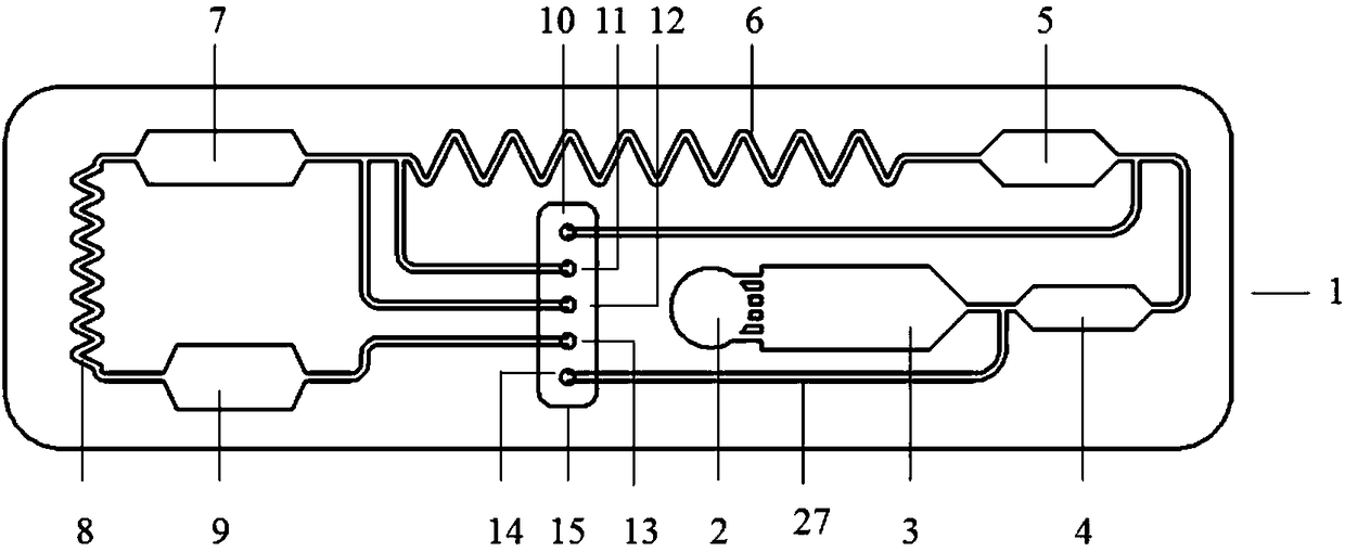
[0043] Please refer to Figure 1 to Figure 5 , this embodiment provides a chemiluminescent microfluidic chip, which includes a chip body, and a sample inlet 2, a liquid driving force inlet 13, a substrate luminescence liquid inlet 11, a cleaning solution inlet 12, Substrate luminescent liquid branch channel 17, cleaning liquid branch channel 18, main fluid channel and multiple functional areas; detailed description will be given below.

[0044] In this embodiment, the main fluid channel communicates with multiple functional areas to guide fluid flow between the functional areas.

[0045] The functional area includes an enzyme-labeled primary antibody embedding area 5 , a magnetic-labeled secondary antibody embedding area 7 and a chemiluminescent detection area 9 which are sequentially connected through the main fluid channel.

[0046] Among them, enzyme-labeled primary antibody embedding area 5 is embedded with enzyme-labeled primary antibody; magnetic-labeled secondary antib...

Embodiment 3

[0067] The description about the liquid quantification area in embodiment 3 is applicable to the description of the liquid quantification area (comprising magnetic label secondary antibody embedding area 7, enzyme-labeled primary antibody embedding area 5 and sample quantification area 4) in this embodiment, here No longer.

Embodiment 4

[0068] The description about the liquid identification site and the liquid identification device in Embodiment 4 is applicable to the description of the liquid identification site and the liquid identification device in this embodiment, and will not be repeated here.

[0069] Optionally, the connection between the other end of the substrate luminescent liquid branch channel 17 and the liquid inlet of the magnetic label secondary antibody embedding area 7 is located on the main fluid channel of the liquid inlet of the magnetic label secondary antibody embedding area 7; In one embodiment, "adjacent" here can generally be understood as "0.5-10 mm (preferably 0.5-2 mm) from the liquid inlet of the magnetic label secondary antibody embedding region 7".

[0070] Optionally, the cleaning liquid enters the magnetic label secondary antibody embedding area 7 through the cleaning liquid inlet 12 and the cleaning liquid branch channel 18 for quantification; the other end of the cleaning li...


PUM

PropertyMeasurementUnit
widthaaaaaaaaaa
heightaaaaaaaaaa
widthaaaaaaaaaa

Abstract

The invention discloses a chemiluminescence micro-fluidic chip, which comprises a chip body, a sample injection port arranged on the chip body, a liquid driving force inlet, a substrate chemiluminescent solution inlet, a rinse-solution inlet, a substrate chemiluminescent solution subchannel, a rinse-solution subchannel, a main fluid channel and multiple functional zones. The main fluid channel iscommunicated with the multiple functional zones. The invention also discloses an analytical instrument containing chemiluminescence micro-fluidic chip. According to the chemiluminescence micro-fluidicchip, identification positioning and quantification of liquid samples are realized through a specific liquid quantification zone, manufacturing difficulty of the chip is reduced, and detection accuracy is raised.

Description

technical field [0001] The invention relates to the technical field of microelectronics, in particular to a chemiluminescence microfluidic chip and an analysis instrument containing it. Background technique [0002] In Vitro Diagnosis (In Vitro Diagnosis, IVD) refers to taking out samples (blood, body fluids, tissues, etc.) from the human body for detection and analysis to diagnose diseases. The detection process requires corresponding instruments and reagents, which consist of in vitro diagnostic system. In vitro diagnostic systems are roughly divided into two types; one is represented by the testing center laboratory, which has system modularization, automation, and pipeline-style sample testing, so it also has high-throughput, high-efficiency, and high-sensitivity. Advantages, but the entire system also has the disadvantages of high cost, large volume, and professional operation. It is mainly used in large hospitals. The other one is represented by point-of-care testing...

Claims


Application Information

Patent Timeline
Patent Type & Authority Applications(China)
IPC IPC(8): G01N21/76B01L3/00
CPCG01N21/76B01L3/5027
Inventor 蒙玄万惠芳胡海升李文美
Owner GUANGZHOU WONDFO BIOTECH
Why Eureka
Try Eureka