Foam production method using liquidizing medium and application of foam production method and firefighting method

A generation method and technology of foam, applied in fire rescue and other fields, can solve the problems of limited gas supply of gas compressors and compressed gas cylinders, no space for layout, and large space occupation, so as to facilitate on-site layout and fire extinguishing work, The effect of strong independent working ability and small footprint

Active Publication Date: 2018-09-14
CHINA PETROLEUM & CHEM CORP +1
View PDF7 Cites 3 Cited by
  • Summary
  • Abstract
  • Description
  • Claims
  • Application Information

AI Technical Summary

Problems solved by technology

Among them, compressed gas foam fire extinguishing usually uses gas compressors, high-pressure gas pipe networks or compressed gas cylinders for gas supply, and the gas supply of gas compressors and compressed gas cylinders is limited, which cannot meet the needs of large flow, high pressure, and long-term supply. However, most places do not have a high-pressure gas pipeline network, and if large flow, high pressure, and long-term gas supply are required, multiple compressors or compressed gas cylinders (such as one with a flow rate of 150L/S Take the foam fire truck as an example, the gas supply flow rate is at least 1050L/s, and its gas supply needs to be supplied by multiple large air compressors), which takes up a lot of space, and there is often no space for layout in the oil depot tank area and equipment area. Not conducive to site layout
[0003] Another type of gas storage foam fire extinguishing usually stores compressed gas in the fire extinguishing agent container. When a large flow rate is spr

Method used


Image

  • Foam production method using liquidizing medium and application of foam production method and firefighting method
  • Foam production method using liquidizing medium and application of foam production method and firefighting method
  • Foam production method using liquidizing medium and application of foam production method and firefighting method

Examples


Example Embodiment

[0020] According to a preferred embodiment of the present invention, the liquefaction medium is at least one of liquid nitrogen, liquid carbon dioxide, liquefied inert gas, and liquefied halogenated hydrocarbon gas.

[0021] Since the liquefied medium is vaporized into a gas under a normal room temperature environment, the gas can be obtained without additional operations. Therefore, the mixing method includes passing the liquefied medium in the form of a liquid stream into the foaming substance for mixing. Since the foaming material is generally at ambient temperature and the mixing is usually carried out at ambient temperature, the liquefied medium vaporizes during the process of entering the mixer and contacting with the foaming material, generating a large amount of gas, and thus foaming.

[0022] Aiming at the problem of the supply of large-flow compressed gas, the present invention avoids the technical route of large-scale air compressor or its unit gas supply, and also avoid...

Example Embodiment

[0067] Example 1

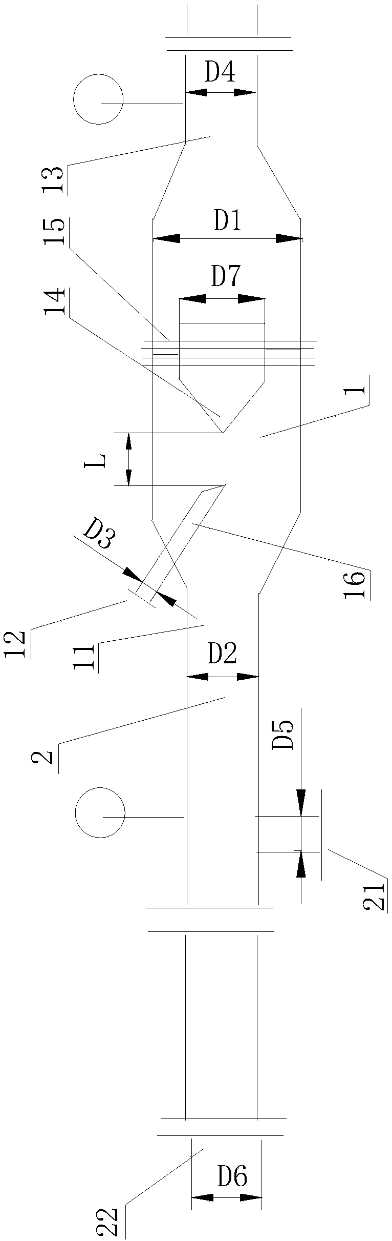
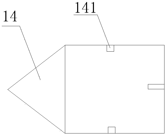
[0068] use figure 1 The mixing device shown is mixed to produce foam, wherein the mixing device has a mixing chamber for mixing liquid nitrogen and foam mixture. The wall of the mixing chamber is provided with a foam mixture inlet, a liquid nitrogen inlet and a Two foam outlets, the foam outlet and the foam mixture inlet are respectively located at the two ends of the cylindrical structure. The relationship between the diameter D2 of the foam mixture inlet and the diameter D3 of the gas inlet is: D2 / D3=8, and the relationship between the diameter D1 of the cylindrical structure and the diameter D2 of the foam liquid inlet is: D1 / D2=1.4, The relationship between the diameter D1 of the cylindrical structure and the diameter D4 of the foam outlet is: D1 / D4=1.2, a spoiler is provided in the mixing chamber, and the spoiler is formed as figure 2 As shown in the conical structure, the conical top of the conical structure faces the foaming substance inlet, the cross s...

Example Embodiment

[0071] Example 2

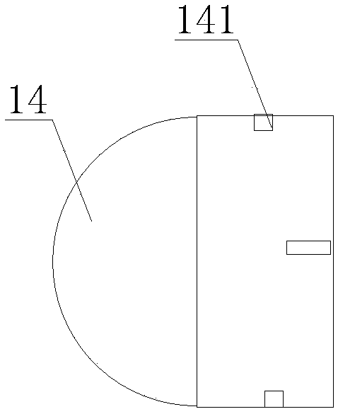
[0072] use figure 1 The mixing device shown is mixed to produce foam, wherein the mixing device has a mixing chamber for mixing liquid nitrogen and foam mixture. The wall of the mixing chamber is provided with a foam mixture inlet, a liquid nitrogen inlet and a Two foam outlets, the foam outlet and the foam mixture inlet are respectively located at the two ends of the cylindrical structure. The relationship between the diameter D2 of the foam mixture inlet and the diameter D3 of the gas inlet is: D2 / D3=10, the relationship between the diameter D1 of the cylindrical structure and the diameter D2 of the foam liquid inlet is: D1 / D2=2, The relationship between the diameter D1 of the cylindrical structure and the diameter D4 of the foam outlet is: D1 / D4=1.2, a spoiler is provided in the mixing chamber, and the spoiler is formed as image 3 As shown in the hemispherical structure, the spherical top of the hemispherical structure faces the foaming substance inlet, the...


PUM


Abstract

The invention discloses a foam production method using a liquidizing medium and the application of the foam production method and a firefighting method. The foam production method comprises the following step: mixing a liquidizing medium with a foaming substance, so as to enable the foaming substance to produce foams. According to the foam production method disclosed by the invention, a mode thata gas generated from the liquidizing medium in situ is mixed with a foaming substance is adopted for a first time, because of a relatively large ratio of the volume of the gas generated from the liquidizing medium to the volume of the liquidizing medium, the volume of a container for storing the liquidizing medium can be greatly reduced, and a large-size air compressor or an air compressor set canbe replaced by small-size storage equipment. In addition, due to the adoption of the liquidizing medium joining in foaming, nitrogen can be released after the foams are broken and takes a combustioninhibition function into play on surfaces of combusted substances, so as to help to accelerate fire extinguishing.

Description

technical field [0001] The present invention relates to foam generation methods and their use in fire extinguishing and fire extinguishing methods. Background technique [0002] Existing compressed gas foam fire extinguishing mainly adopts the mode of mixing high-pressure gas and foam mixture to generate foam to extinguish fire. The specific foam fire extinguishing methods mainly include two kinds of pressure-stabilized compressed gas foam fire extinguishing and gas storage foam fire extinguishing. Among them, compressed gas foam fire extinguishing usually uses gas compressors, high-pressure gas pipe networks or compressed gas cylinders for gas supply, and the gas supply of gas compressors and compressed gas cylinders is limited, which cannot meet the needs of large flow, high pressure, and long-term supply. However, most places do not have a high-pressure gas pipeline network, and if large flow, high pressure, and long-term gas supply are required, multiple compressors or ...

Claims


Application Information

Patent Timeline
IPC IPC(8): A62C5/02A62C31/12
CPCA62C5/02A62C31/12
Inventor 牟小冬郎需庆牟善军姜春明王林厉建祥尚祖政吴京峰谈龙妹于辉陶彬刘全桢
Owner CHINA PETROLEUM & CHEM CORP
Why Eureka
Try Eureka