
Tool-changing machining method based on CCD camera in-situ measurement

A technology of camera and knife method, applied in metal processing, metal processing equipment, measuring/indicating equipment, etc., can solve the problems of tool wear, low processing efficiency, workpiece hardness, strength and other performance degradation, so as to reduce processing costs and improve The effect of processing efficiency and avoiding time cost

Active Publication Date: 2018-09-14
BEIJING INSTITUTE OF TECHNOLOGYGY
View PDF7 Cites 4 Cited by
  • Summary
  • Abstract
  • Description
  • Claims
  • Application Information

AI Technical Summary

Problems solved by technology

Although the tool wear can be appropriately reduced, the processing efficiency is very low, and it still cannot meet the needs of high-efficiency, large-area micro-nano array cutting.
[0005] The method of material modification can transform the surface layer of the processed material into a softer and easy-to-process material, but the thickness of the denatured layer is difficult to ensure uniformity, and it is difficult to ensure that the cutting depth is consistent with the thickness of the deformed layer during cutting
Therefore, when the depth of cut is greater than the thickness of the denatured layer, the tool tip is equivalent to directly processing hard materials, and the tool wears seriously; when the depth of cut is less than the thickness of the denatured layer, tool wear can be effectively avoided, but the residual denatured layer on the workpiece surface will cause hardness, strength, etc. The performance is degraded and cannot meet the requirements of use

Method used


Image

  • Tool-changing machining method based on CCD camera in-situ measurement
  • Tool-changing machining method based on CCD camera in-situ measurement
  • Tool-changing machining method based on CCD camera in-situ measurement

Examples


Embodiment Construction

[0038] The following will clearly and completely describe the technical solutions in the embodiments of the present invention with reference to the accompanying drawings in the embodiments of the present invention. Obviously, the described embodiments are only some, not all, embodiments of the present invention. Based on the embodiments of the present invention, all other embodiments obtained by persons of ordinary skill in the art without making creative efforts belong to the protection scope of the present invention.

[0039] The purpose of the present invention is to provide a tool-changing processing method based on in-situ measurement of a CCD camera to realize high-quality, large-area micro-nano array processing on superhard materials.

[0040] In order to make the above objects, features and advantages of the present invention more comprehensible, the present invention will be further described in detail below in conjunction with the accompanying drawings and specific em...


PUM


Abstract

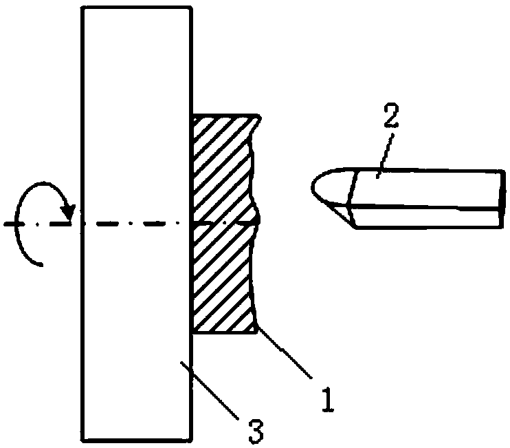
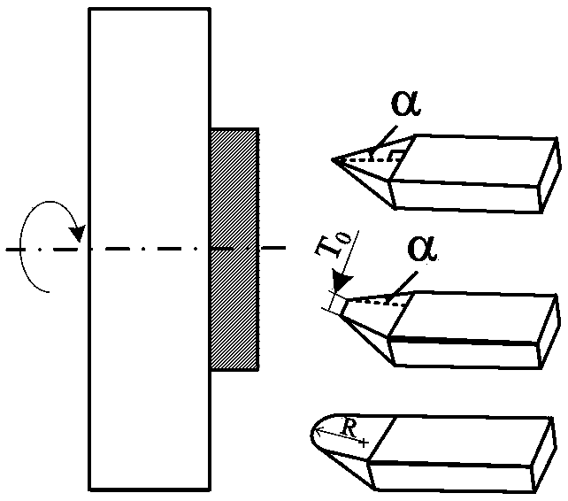
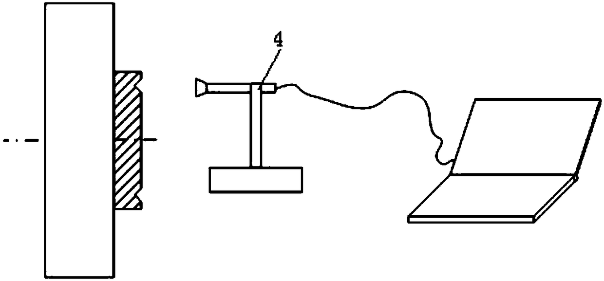
The invention discloses a tool-changing machining method based on CCD camera in-situ measurement. The method comprises the steps that the width of a circular ring is obtained through CCD camera measurement; and the reference position of a machined plane of a workpiece is modified according to the width of the circular ring; subsequent machining is conducted with the reference position as the reference; and after a tool is worn to a certain degree, a sequential process including primary feeding, calculation and secondary feeding is implemented for a newly-mounted tool. By means of the method, precise machining of a microstructural array with the machining depth being D is achieved.

Description

technical field [0001] The invention relates to the technical field of ultra-precision cutting, in particular to a tool-changing machining method based on in-situ measurement of a CCD camera. Background technique [0002] In the process of mechanical processing, it is often necessary to determine the reference plane before processing. Especially in the field of ultra-precision machining, the positioning accuracy of the reference plane directly affects the machining accuracy. However, when single crystal diamond is used for ultra-precision cutting of superhard materials such as WC, the tool wear is serious. If the original reference plane is used for processing, it is difficult to complete high-quality, large-area micro-nano array cutting. [0003] The existing technology mainly adopts methods such as reducing the cutting thickness, using a large negative rake tool, and surface modification of the material to realize ultra-precision cutting of large-area, high-quality micro-...

Claims


Application Information

Patent Timeline
IPC IPC(8): B23B1/00B23Q15/14B23Q17/00B23Q17/24
CPCB23B1/00B23Q15/14B23Q17/002B23Q17/249
Inventor 周天丰阮本帅周佳董晓彬梁志强王西彬
Owner BEIJING INSTITUTE OF TECHNOLOGYGY
Learn More