Welding seam trajectory offline calibration method based on structured light visual sensor

A vision sensor and calibration method technology, applied in welding equipment, auxiliary welding equipment, welding/cutting auxiliary equipment, etc., can solve the problem of no matching calibration and achieve good track calibration and strong applicability

Inactive Publication Date: 2018-09-14
SOUTH CHINA UNIV OF TECH +1
View PDF7 Cites 20 Cited by
  • Summary
  • Abstract
  • Description
  • Claims
  • Application Information

AI Technical Summary

Problems solved by technology

There are few applications for off-line trajectory calibration of the weld trajectory, and many applications only detect the weld trajectory without the process of matching calibration

Method used


Image

  • Welding seam trajectory offline calibration method based on structured light visual sensor
  • Welding seam trajectory offline calibration method based on structured light visual sensor
  • Welding seam trajectory offline calibration method based on structured light visual sensor

Examples


Embodiment 1

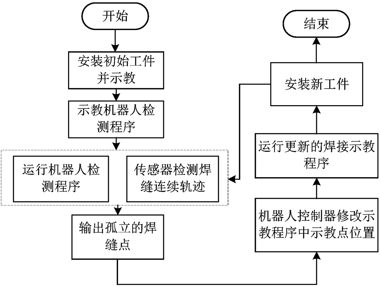
[0045] Such as figure 1 As shown, an off-line calibration method of weld trajectory based on structured light vision sensor, including steps:

[0046] Step 1. Teach the initial workpiece, and obtain the teaching track and teaching point of the initial workpiece;

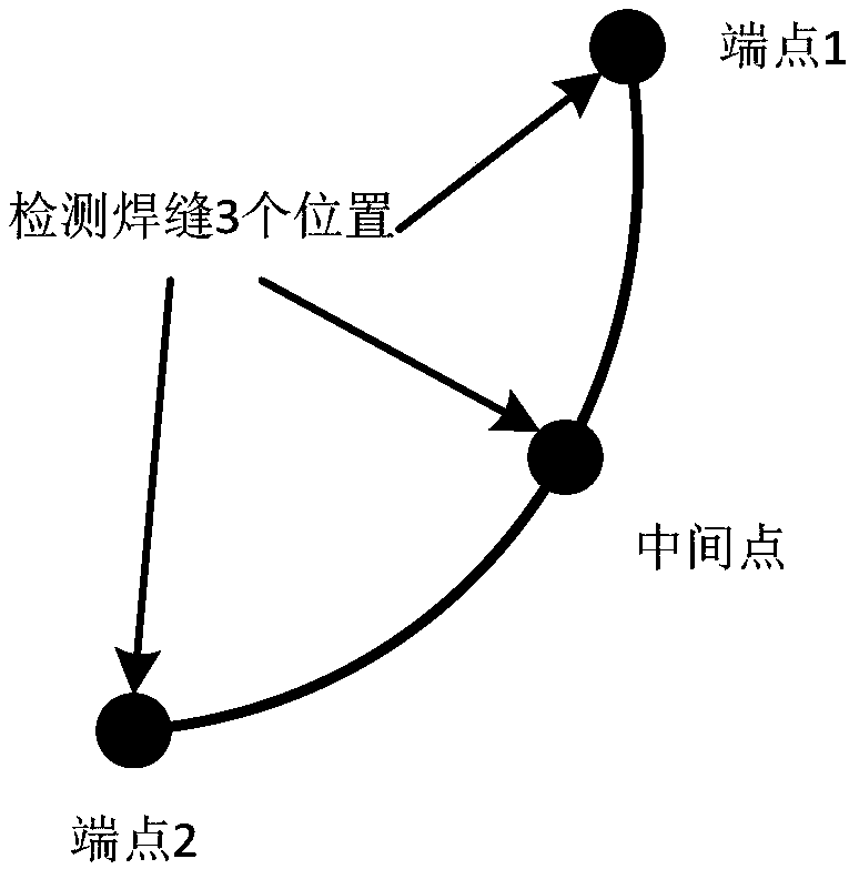
[0047] Step 2. When the form of the weld is a simple regular weld, according to the structural form of the weld, select a number of specific weld point positions that can reflect the form of the weld; teach the robot detection program to ensure that the structured light vision sensor can detect all Selected specific weld point locations;

[0048] Step 3, run the welding seam detection program, the robot moves to the position of each selected specific welding seam point, and the structured light vision sensor detects the position information of each specific welding seam point of the current laser line;

[0049] Step 4, extracting the position information of each detected specific welding seam point, and transmittin...

Embodiment 2

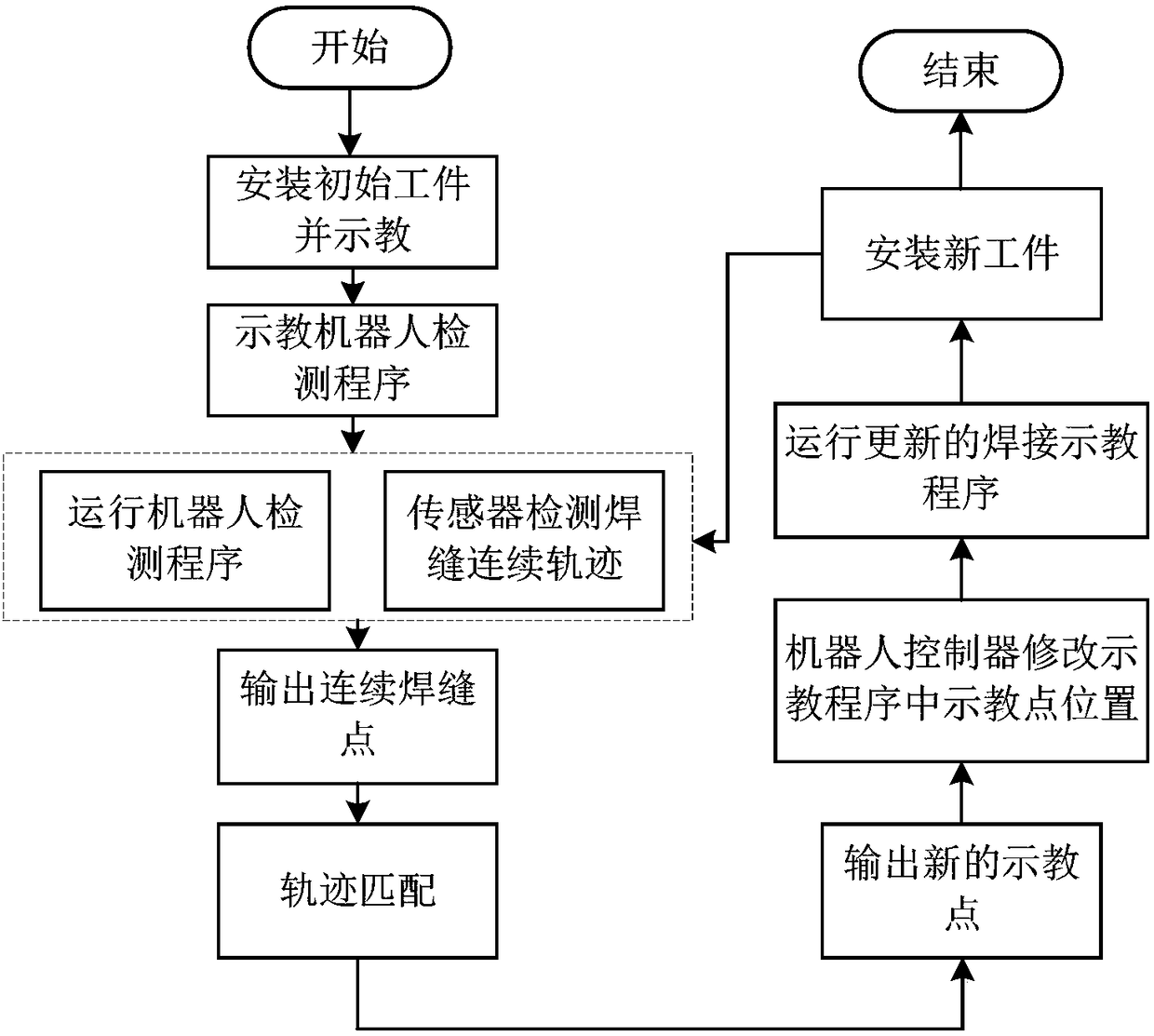
[0055] Such as image 3 As shown, an off-line calibration method of weld trajectory based on structured light vision sensor, including steps:

[0056] Step 1. Teach the initial workpiece, and obtain the teaching track and teaching point of the initial workpiece;

[0057] Step 2. When the weld seam is an irregular and complex weld seam, according to the structural form of the workpiece weld seam, teach the robot weld seam inspection program, so that the structured light vision sensor can detect the continuous trajectory of the entire weld seam;

[0058] Step 3. Run the welding seam inspection program, the robot starts to continuously inspect the entire welding seam of the workpiece from the starting position, and obtains the continuous trajectory points of the welding seam;

[0059] Step 4. Transmit the detected corresponding weld point position information to the robot controller to modify the teaching point position in the initial teaching program, specifically including:

...


PUM


Abstract

The invention discloses a welding seam trajectory offline calibration method based on a structured light visual sensor. The method comprises the following steps that step 1, a teaching track and a teaching point of an initial workpiece are obtained through teaching; step 2, a teaching robot detecting program is carried out, a corresponding weld joint point position is guaranteed be detected by thestructured light visual sensor; step 3, the robot is enabled to drive the structured light visual sensor according to a corresponding movement mode to detect a weld joint point position information corresponding to a current laser line; step 4, the detected corresponding weld joint point position information is transmitted to a robot controller to modify a teaching point position in an initial teaching program; step 5, the modified robot welding teaching program is carried out, and a robot moves according to the modified teaching program to complete the welding seam trajectory calibration; and step 6, after the welding is completed, a new workpiece is installed, and the step 3 to the step 5 are repeated. According to the method, the requirement for the workpiece positioning is reduced, sothat the deviation of the welding seam of the workpiece can be effectively solved, and the flexibility of the welding robot is improved.

Description

technical field [0001] The invention belongs to the field of robot intelligent welding, and relates to an off-line calibration method of a weld track based on a structured light vision sensor. Background technique [0002] The vast majority of robots used in the field of welding are taught and reproduced. However, due to the inconsistency of the shape and size of the workpiece to be welded and the low positioning accuracy of the fixture, the traditional teaching and reproduction method can no longer meet the welding requirements. One way to solve this problem is to improve the machining accuracy of the workpiece and the positioning accuracy of the fixture, but this method will significantly increase the production cost, and the precision of the processing equipment and the technical requirements of the workers are high. For complex workpieces , The design requirements of high-precision fixtures are high, and the accuracy of fixtures will decrease with the increase of use ti...

Claims


Application Information

Patent Timeline
Patent Type & Authority Applications(China)
IPC IPC(8): B25J9/00B23K37/00
CPCB23K37/00B25J9/0081
Inventor 王念峰石小东郑永忠周升勇
Owner SOUTH CHINA UNIV OF TECH
Why Eureka
Try Eureka