Check patentability & draft patents in minutes with Patsnap Eureka AI!

Burner and heat treatment facility

A heat treatment and burner technology, applied in the field of burner devices and heat treatment equipment, can solve the problems of unstable air flow, difficult combustion of mixed gas, difficulty in flame, etc.

Inactive Publication Date: 2018-09-14
CHUGAI RO CO LTD
View PDF12 Cites 0 Cited by
  • Summary
  • Abstract
  • Description
  • Claims
  • Application Information

AI Technical Summary

Problems solved by technology

[0007] However, in the technology described in Patent Document 1, since the mixed gas obtained by pre-mixing fuel gas and air is guided to the injection hole forming portion provided at the front end portion of the burner main body, The flame at the inclined portion of the hole forming portion keeps the mixed gas ejected from the forming hole burning in the protective portion, so there is a problem that it becomes difficult to stably burn the mixed gas if the amount of fuel gas in the mixed gas is reduced
[0009] However, in the technology described in Patent Document 2, since only the passage port for injecting fuel is opened in the central portion of the inverted conical body, and the fuel is injected from the passage port in the central portion, it is necessary to reduce the amount of injected fuel. In this case, the fuel injected from the passage port in the central part may not be fully contacted and combusted with the combustion air sprayed forward and rotated through the front slit and the rear slit, so there is still the following problem: Reliably maintaining the flame becomes difficult with fuel
[0011] However, the technologies shown in Patent Documents 3 and 4 still have the problem that it becomes difficult to reliably maintain the flame in the case of reducing the injected fuel.
[0012] In addition, in the heat treatment apparatus described in Patent Document 5, a pair of heat storage chambers containing a heat storage material are provided near the burner device. The following actions of the regenerators are alternately switched: In one regenerator, the combustion air is heated by the heat accumulated in the regenerator stored in the regenerator, and the heated combustion air flows from The fuel gas ejected from the fuel gas supply pipe of the above-mentioned burner device is injected to burn the fuel gas, and in the other regenerator chamber, the combustion exhaust gas after the fuel gas is burned is sucked into the heat storage chamber accommodated in the regenerator. material and store the heat of the combustion exhaust gas in the heat storage material, since it takes several seconds to open and close the switching valve that switches the injection and suction of combustion air, the air flow becomes unstable during this period, so the current This is done by cutting off the supply of fuel gas and extinguishing the flame
Therefore, it is necessary to install an ignition device such as a pilot burner or an electric ignition device, and to re-ignite every time the combustion air is switched, so that there is a problem that the structure and control of the combustion device become complicated.
In addition, if the flame is extinguished, it becomes difficult to maintain the temperature of the air near the burner device, so the above-mentioned method will also cause the temperature in the furnace to fluctuate.

Method used


Image

  • Burner and heat treatment facility
  • Burner and heat treatment facility
  • Burner and heat treatment facility

Examples


Embodiment Construction

[0067] Hereinafter, the burner apparatus and heat treatment facility which concerns on embodiment of this invention are demonstrated concretely based on drawing. In addition, the burner device and the heat treatment facility of the present invention are not limited to the devices and facilities shown in the following embodiments, and can be appropriately changed and implemented within the range not changing the idea of ​​the invention.

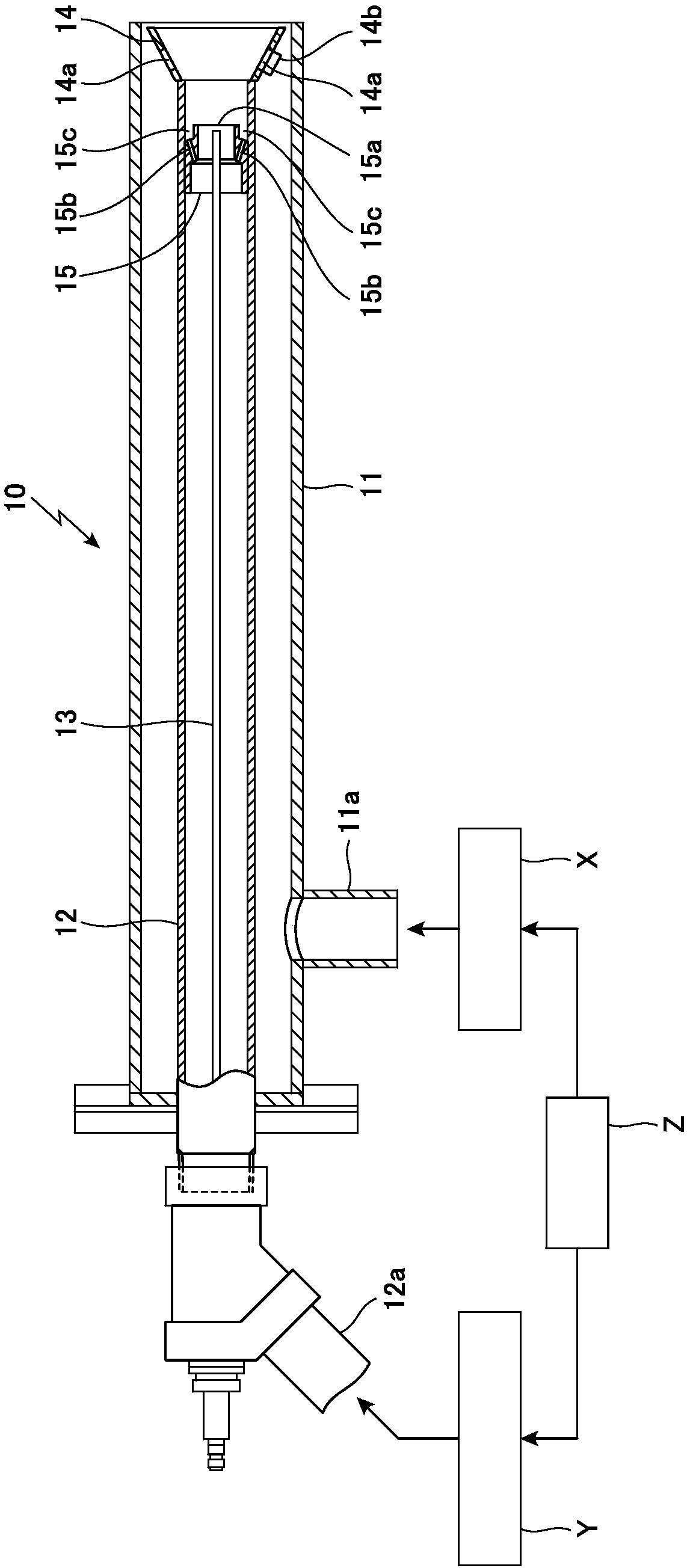
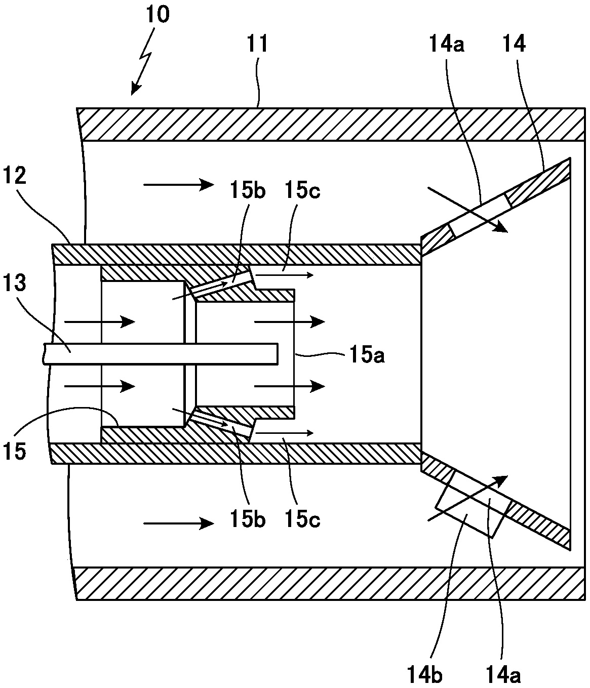
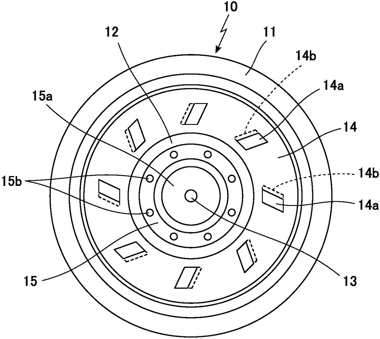
[0068] In the burner device 10 of the present embodiment, as figure 1 As shown, air is supplied from the air introduction part 11a into the air supply pipe 11 by the air supply device X, and fuel gas is supplied from the fuel gas introduction part 12a to the air supply pipe 11 arranged by the fuel gas supply device Y. In the fuel gas supply pipe 12 on the inner peripheral side, the amount of air supplied to the air supply pipe 11 by the above-mentioned air supply device X and the amount of fuel supplied to the fuel gas supply pipe 12 by the fu...


PUM


Abstract

The invention discloses a burner and a heat treatment facility using the same. When the burner mixes and burns fuel gas, which is guided by a fuel gas supplying pipe arranged on the inner periphery ofan air supplying pipe, and air, which is guided by the air supply pipe, the front end of the fuel gas supplying pipe is provided with a flame keeping cylinder, which faces the front and conically extends to the outer periphery. The flame keeping cylinder is provided with an air leading-in hole and an air guiding part, which introduce air in the air supplying pipe into the flame keeping cylinder.The front end of the fuel gas supplying pipe is provided with a main jet orifice, from which fuel gas is ejected from the center of the fuel gas supplying pipe, and a plurality of auxiliary jet orifices, through which the fuel gas is ejected from the periphery of the main jet orifice. The burner is provided with a control device, which controls the quantities of the fuel gas and / or air.

Description

technical field [0001] The present invention relates to a burner device and heat treatment equipment using the above-mentioned burner device. A fuel gas supply pipe is provided on the inner peripheral side of the air supply pipe of the above-mentioned burner device. The fuel gas and the air guided to the outer peripheral side of the fuel gas supply pipe via the air supply pipe are mixed and burned. In particular, in the above-mentioned burner device, there is a feature that even in the case of reducing the amount of fuel gas guided via the fuel gas supply pipe, the above-mentioned fuel gas can be combined with the fuel gas guided to the fuel gas supply pipe via the air supply pipe. The air on the outer peripheral side is properly mixed to maintain the flame properly, and the turndown ratio of the burner can be increased. Background technique [0002] At present, a burner device is widely used in heat treatment equipment such as industrial furnaces. A fuel gas supply pipe is...

Claims


Application Information

Patent Timeline
Patent Type & Authority Applications(China)
IPC IPC(8): F23D14/08F23D14/60
CPCF23D14/085F23D14/60Y02E20/34F23D14/22F23D14/58F23D14/66
Inventor 友泽健一河本祐作片山智树丁骁腾作部屋幸嗣
Owner CHUGAI RO CO LTD
Features
  • R&D
  • Intellectual Property
  • Life Sciences
  • Materials
  • Tech Scout
  • Unparalleled Data Quality
  • Higher Quality Content
  • 60% Fewer Hallucinations
Learn More