Dubins path based obstacle avoidance control device and method for driverless car

An unmanned vehicle and control device technology, applied in vehicle position/route/altitude control, two-dimensional position/airway control, non-electric variable control and other directions, can solve cognitive defects, intelligent car processor can not correctly confirm Knowing the problems of vehicles, pedestrians, and unreliable driverless technology, to achieve the effect of improving the integrity

Active Publication Date: 2018-09-14
JILIN UNIV
View PDF8 Cites 30 Cited by
  • Summary
  • Abstract
  • Description
  • Claims
  • Application Information

AI Technical Summary

Problems solved by technology

[0003] However, the current unmanned driving technology mainly has the following two problems: 1. There are identification obstacles in the sensor, the perception of the surrounding environment by radar and camera is greatly affected by the weather and the environment, the sensor technology is not perfect and there are often monitoring dead spots, Unable to accurately obtain information about nearby obstacles; 2. Smart car processors cannot correctly recognize the behavior of vehicles and pedestrians like the human brain, and have cognitive defects; 3. People do not trust driverless technology
[0004] The first two major problems both lead to the inability of unmanned vehicles to accurately avoid obstacles, and also exacerbate the third problem. At this stage, many patents do not solve the problem of unmanned vehicle obstacle avoidance.
[0005] The patent application number 201610782894.3 discloses a laser obstacle avoidance method and system for unmanned vehicles. The system includes a driving control module, a laser component, and an autonomous obstacle avoidance module. To control the driving of unmanned vehicles, the laser transmitter sends las...

Method used


Image

  • Dubins path based obstacle avoidance control device and method for driverless car
  • Dubins path based obstacle avoidance control device and method for driverless car
  • Dubins path based obstacle avoidance control device and method for driverless car

Examples


Embodiment Construction

[0098] The present invention is described in detail below in conjunction with accompanying drawing:

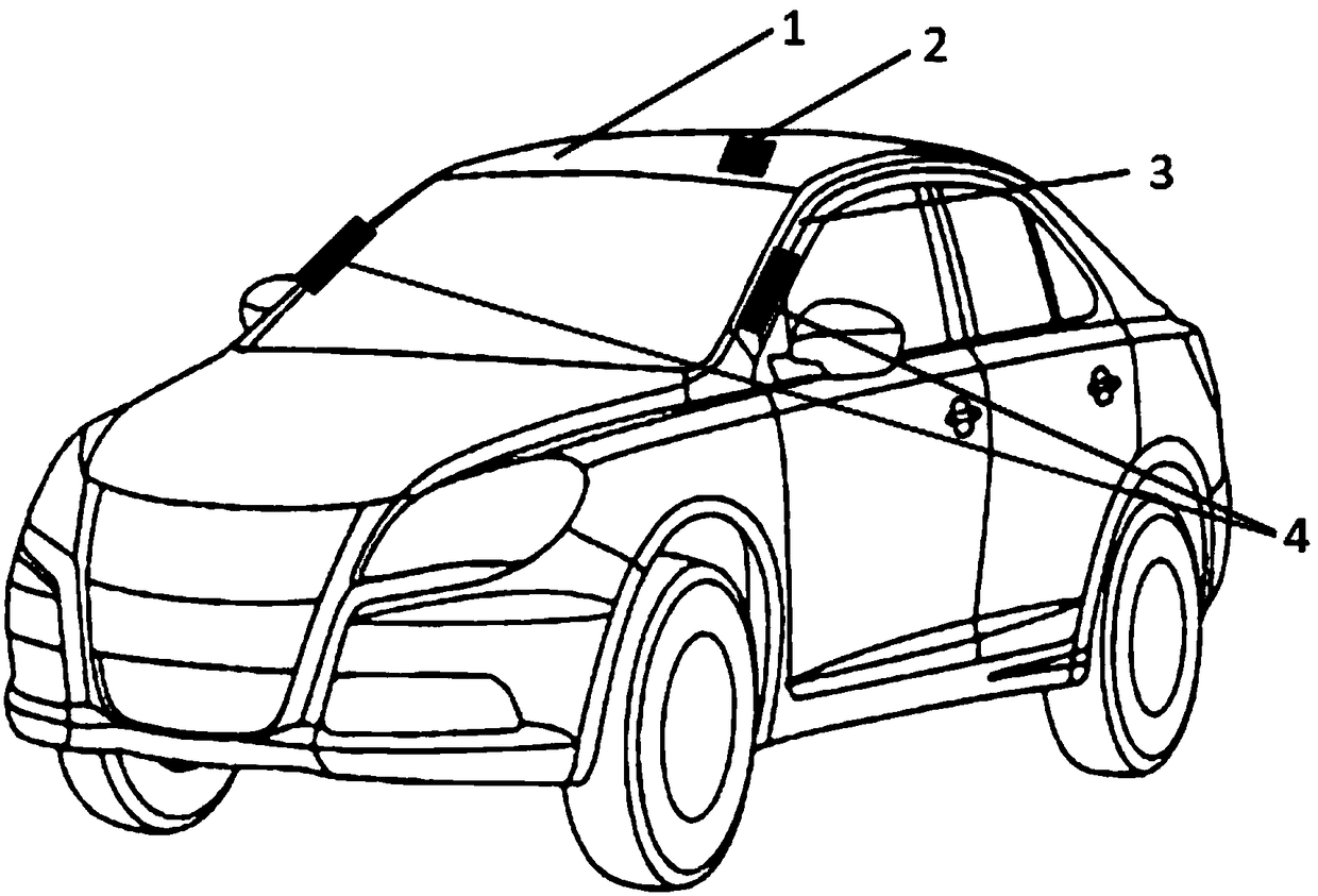
[0099] A kind of unmanned vehicle obstacle avoidance control device based on Dubins path, it is characterized in that, comprise a camera 4 that is arranged on the outside of A column 3 on the left side of unmanned vehicle, a camera 4 that is arranged on the outside of A column 3 on the right side of unmanned vehicle A camera 4 and a lidar 2 installed on the roof 1 of the unmanned vehicle, the two cameras 4 are located in the middle of the A-pillar 3 and on the same horizontal line, and the center of mass of the lidar 2 and the unmanned vehicle is on the same straight line , and the line is perpendicular to the horizontal plane. Such as figure 1 shown;

[0100] The camera 4 is arranged on the left and right A-pillars 3 outside the unmanned vehicle, which is beneficial to solve the problem of blind spots in the unmanned vehicle;

[0101] A kind of unmanned vehicle obstacle av...


PUM


Abstract

The invention provides a Dubins path based obstacle avoidance control device and method for a driverless car. The device comprises a camera arranged outside the left A pillar of the driverless car, acamera arranged outside the right A pillar of the driverless car as well as a laser radar arranged on the roof of the driverless car. The method comprises the following steps: the radar performs positioning and speed measurement on obstacles entering a camera monitoring range; a sequence of an obstacle to collide with the smart car is determined with an obstacle avoidance algorithm; the smart carreplans the current obstacle avoidance path according to the new obstacle sequence to finish the obstacle avoidance operation. By arranging the cameras in the middles of the two A pillars of the driverless car, the problem about bind area of the driverless car is solved effectively, and perfect and accurate degree of information acquisition is increased; different obstacle avoidance judgment algorithms are adopted for different obstacles in driverless operation, and obstacle avoidance accuracy and precision of the driverless car are improved.

Description

technical field [0001] The invention belongs to the field of automobiles, and relates to an unmanned vehicle obstacle avoidance control device and control method based on Dubins path. Background technique [0002] With the continuous development and improvement of automobile technology, unmanned driving technology has emerged in due course. Unmanned driving relies on the cooperation of artificial intelligence, visual computing, radar, monitoring devices and global positioning systems, allowing computers to operate without any active human operation. , to automatically and safely operate motor vehicles. Its main principle is to perceive the road environment through the vehicle-mounted sensor system, automatically plan the driving route and control the vehicle to reach the predetermined target; at the same time, the vehicle-mounted sensor senses the surrounding environment, and controls the vehicle's movement according to the road, vehicle position and obstacle information obt...

Claims


Application Information

Patent Timeline
IPC IPC(8): G05D1/02
CPCG05D1/0214G05D1/0221G05D1/0223G05D1/024G05D1/0246G05D1/0257G05D1/0276G05D2201/0212Y02T10/40
Inventor 何磊宋琪曹起铭李成宏
Owner JILIN UNIV
Why Eureka
Try Eureka