
Transmission mechanism for 40.5kV switch cabinet isolation switch

A technology of isolating switch and transmission mechanism, which is applied in the direction of electric switch, air switch parts, high-voltage air circuit breaker, etc., which can solve the problems of unfavorable switch cabinet normal use, AC skin effect, conductive circuit overheating, etc., and facilitates industrial production , Occupy small space, high reliability effect

Pending Publication Date: 2018-09-14
ASIA ELECTRICAL POWER EQUIP SHENZHEN CO LTD
View PDF0 Cites 2 Cited by
  • Summary
  • Abstract
  • Description
  • Claims
  • Application Information

AI Technical Summary

Problems solved by technology

[0003] At present, for 40.5kV power transmission and transformation switchgear, high-voltage isolating switches generally use GN27 or GN2 rotary structure isolating switches. Such products are used for 40.5kV level switchgear, and often have phenomena such as conductive circuit overheating and operation failure. , and its bulky size makes it difficult to transport
At the same time, during the opening and closing operation of this type of product, the movement direction of the contact is to rotate and open or close along the arc direction. In order to ensure that the isolation fracture of the product has a sufficient safety distance, it is required that the components of the product be in close contact with each other. The distance is too large, so that the installation area is very large; and when the isolation knife is installed in the switch cabinet with high current, the skin effect of alternating current is easy to occur, which is not conducive to the normal use of the switch cabinet

Method used


Image

  • Transmission mechanism for 40.5kV switch cabinet isolation switch
  • Transmission mechanism for 40.5kV switch cabinet isolation switch
  • Transmission mechanism for 40.5kV switch cabinet isolation switch

Examples


Embodiment 1

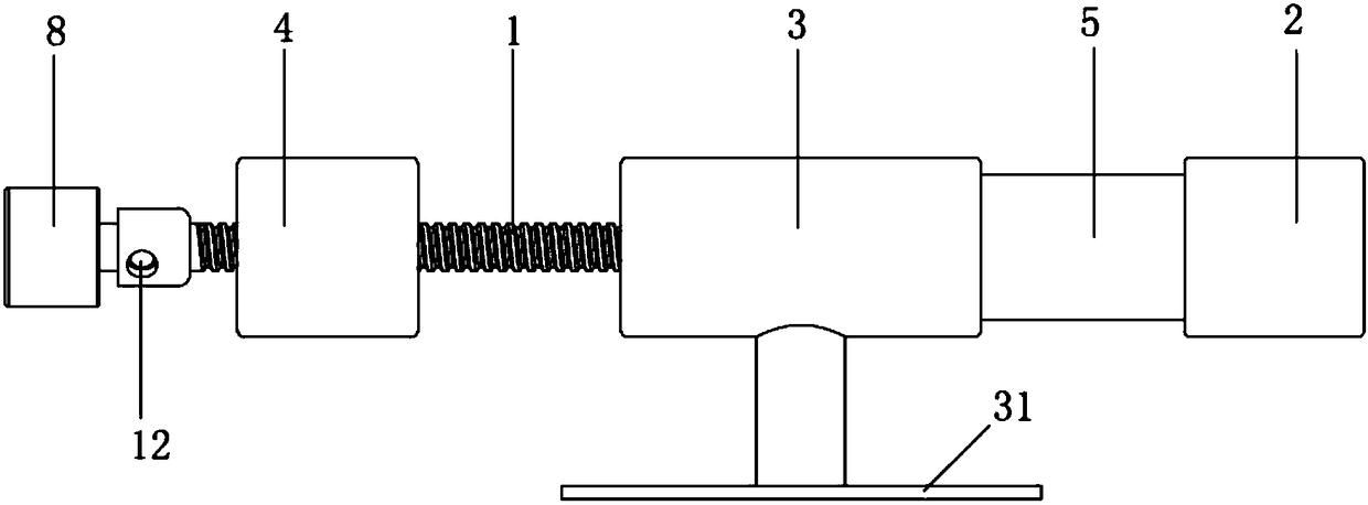
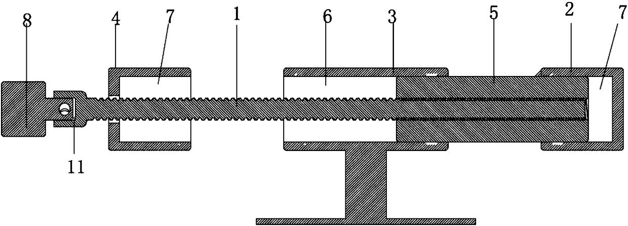
[0024] Such as Figure 1 to Figure 2 As shown, a transmission mechanism for a 40.5kV switchgear isolating switch shown in this embodiment includes an insulating screw 1, and a grounding contact 4 is sequentially sleeved on the screw thread at the position from the head to the tail of the insulating screw 1 , insulated moving contact bracket 3 and static contact 2, and the grounding contact 4, moving contact bracket 3 and static contact 2 are all fixed on the switchgear (not shown in the figure) and do not contact the insulating screw 1 , a through hole 6 is provided on the moving contact bracket 3, the insulating screw 1 passes through the through hole 6, and the moving contact 5 is arranged in the through hole 6, and the moving contact 5 and the insulating screw 1 are connected by threads One end of the ground contact 4 and the static contact 2 close to the movable contact bracket 3 is provided with a slot 7 for accommodating the movable contact 5, and the movable contact 5 c...

Embodiment 2

[0027] Such as figure 1 and figure 2 As shown, a transmission mechanism for a 40.5kV switch cabinet isolating switch shown in this embodiment, on the basis of the structure described in Embodiment 1, is connected to the head of the insulating screw 1 for driving the rotation of the insulating screw 1 The motor 8 is fixed on the switch cabinet.

[0028] Specifically, the outer end surface of the head of the insulating screw 1 is provided with a fixing hole 11 for accommodating the rotating shaft of the motor 8, and the insulating screw 1 and the rotating shaft of the motor 8 within the range of the fixing hole 11 are provided with corresponding pin holes 12, through which the pins Through the pin hole 12, the rotating shaft of the motor 8 is fixed in the fixed hole 11, and the moving contact moves back and forth on the insulating screw through the forward rotation and reverse rotation of the motor, and the automatic control and closing of the grounding contact or the static c...

Embodiment 3

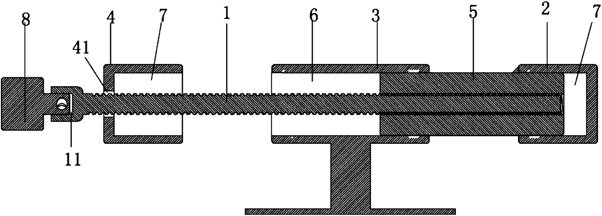
[0030] Such as figure 1 and image 3 As shown in this embodiment, a transmission mechanism for a 40.5kV switchgear isolating switch, on the basis of the structure described in Embodiment 2, the end of the static contact 2 away from the moving contact bracket 3 is closed , so that the tail of the insulating screw 1 is placed in the slot 7 in the static contact 2 to ensure that the movable contact can move into the slot 7 in the static contact 2; There is a shaft hole 41 for the insulating screw 1 to pass through, and the diameter of the shaft hole 41 is larger than that of the insulating screw 1 .

[0031] Specifically, the through hole 6 and the slot 7 are square holes with the same size, and the moving contact 5 is a square shape with the same size as the square hole; the length of the moving contact 5 is longer than that of the moving contact bracket 3 and the side of the slot 7 The distance between the walls is such that after the moving contact 5 enters the slot 7, the e...


PUM


Abstract

The present invention discloses a transmission mechanism for a 40.5kV switch cabinet isolation switch. The mechanism comprises an insulation screw, the insulation screw is sleeved with a ground contact, a movable contact support and a static contact which are fixed on a switch cabinet in order in the axial direction, the movable contact support is provided with a through hole configured to allow the insulation screw to pass through, the through hole is internally provided with a movable contact being in threaded connection with the insulation screw, one ends, close to the movable contact support, of the ground contact and the static contact are provided with slotted holes holding the movable contact, the movable contact is moved left and right into the slotted holes with the rotation of the insulation screw, the length of the movable contact is smaller than a distance between the static contact and the ground contact, and the length of the movable contact is larger than a distance between the static contact and the movable contact support and a distance between the ground contact and the movable contact support. The transmission mechanism is simple in structure, convenient to transport, install and operate, high in reliability and free of maintenance and little in maintenance.

Description

technical field [0001] The invention relates to the technical field of high-voltage isolating switches, in particular to a transmission mechanism for a 40.5kV switch cabinet isolating switch. Background technique [0002] The high-voltage switchgear isolating switch is mainly used for line conversion in high-voltage lines. In order to improve the reliability of power supply, intelligent, miniaturized, and maintenance-free switchgear is the development trend of the power industry. Among them, the switchgear generally installs high-voltage components such as vacuum circuit breakers, isolating switches, busbars and transformers in the upper and lower isolation chambers, and the isolation chambers are filled with SF6 gas as the insulating medium to reduce the overall size of the cabinet, thereby realizing the miniaturization of the inflatable cabinet and operational reliability. In the power transmission and transformation equipment of the power system, the high-voltage isolati...

Claims


Application Information

Patent Timeline
Patent Type & Authority Applications(China)
IPC IPC(8): H01H31/02
CPCH01H31/026
Inventor 郭予龙高向华杜立春娄清宇
Owner ASIA ELECTRICAL POWER EQUIP SHENZHEN CO LTD
Learn More