A jacking mechanism for a stamping die

A technology of ejecting mechanism and stamping die, which is applied to forming tools, manufacturing tools, metal processing equipment, etc., can solve the problems that the ejecting mechanism does not have dust removal function, is inconvenient for buffer strength, and is inconvenient for heat dissipation of workpieces, and achieves increased stability. , Safe and convenient to use, press down and push out stable effect

Active Publication Date: 2020-01-03
鹏得精密科技(深圳)有限公司
View PDF8 Cites 0 Cited by
  • Summary
  • Abstract
  • Description
  • Claims
  • Application Information

AI Technical Summary

Problems solved by technology

[0003] After searching, the Chinese patent discloses a metal stamping die ejector mechanism (authorized announcement number CN206763790U). This patented technology can select different ejector methods according to the ground contact force between the workpiece and the lower die seat, which greatly improves the stamping process. The ejection efficiency of the mold improves the extraction efficiency of the workpiece and saves the workload of the ejection after the stamping process, but it is not convenient to buffer the force generated by the workpiece during the initial pressing process, which makes the stability of the workpiece when it is pressed and pushed out. Poor, and the ejector mechanism itself does not have the function of dust removal, and it is not convenient to dissipate heat from the bottom of the workpiece. At the same time, it is cumbersome to operate. Therefore, we propose a ejector mechanism for stamping dies.

Method used


Image

  • A jacking mechanism for a stamping die
  • A jacking mechanism for a stamping die
  • A jacking mechanism for a stamping die

Examples


Embodiment Construction

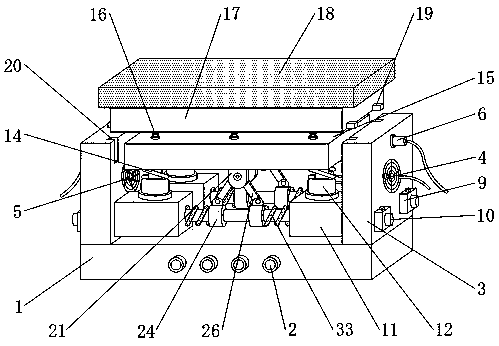
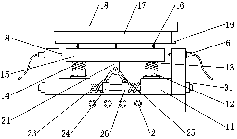
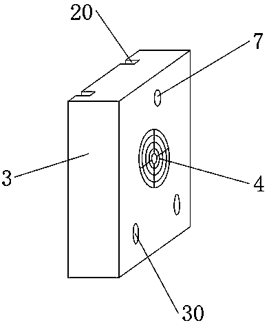
[0029] see Figure 1-7 , in an embodiment of the present invention, a material ejecting mechanism for a stamping die includes a fixed seat 1, a control button 2 is provided on the front surface of the fixed seat 1, and two side plates are connected to the top edge of the fixed seat 1 in a symmetrical structure 3. A tuyere 4 is set in the middle of the side plate 3, a fan 5 is installed inside the tuyere 4, a hydraulic telescopic rod 6 is installed on the outer wall of the side plate 3 above the tuyere 4, and the output end of the hydraulic telescopic rod 6 is located on the side plate 3 The inner side of the side plate 3 is connected with a block 8, and the inside of the side plate 3 is provided with a first fixing hole 7 corresponding to the output end of the hydraulic telescopic rod 6. Block 9, the middle part of the fixed block 9 is located above the fixed seat 1 and is inserted with a fixed rod 10, and the inside of the fixed block 9 is provided with a fourth fixed hole 32...


PUM


Abstract

The invention discloses an ejection mechanism of a stamping die. The ejection mechanism comprises a fixing base, a control button is arranged on the front surface of the fixing base, two side plates are connected to the edge of the top end of the fixing base in a symmetrical-structure manner, an air opening is formed in the middle portion of each side plate and is internally provided with a fan, ahydraulic expansion link is installed at the position, located above the corresponding air opening, of the outer side wall of each side plate, a clamping block is connected to the position, located on the inner side of the corresponding side plate, of the output end of each hydraulic expansion link, a first fixing hole is formed in the position, corresponding to the exterior of the output end ofthe corresponding hydraulic expansion link, inside each side plate, and fixing blocks are connected to the positions, located on the two sides of the lower portion of the corresponding air opening, ofthe outer side wall of each side plate. By means of the ejection mechanism, force generated by a workpiece in the initial pressing process can be buffered in actual work, the working stability of thestamping die is increased, the mechanism has the dustproof effect, meanwhile, the workpiece bottom can be cooled, and operation is simpler.

Description

technical field [0001] The invention relates to the technical field of molds, in particular to a material ejecting mechanism of a stamping mold. Background technique [0002] Stamping die is a special process equipment for processing materials (metal or non-metal) into parts (or semi-finished products) in cold stamping processing. It is called cold stamping die (commonly known as cold stamping die). Stamping is installed at room temperature The mold on the press presses the material to cause separation or plastic deformation to obtain a press processing method for the required parts. The materials for manufacturing stamping molds include steel, hard alloy, steel-bonded hard alloy, and zinc-based Alloys, low melting point alloys, aluminum bronze, polymer materials, etc., after the stamping is completed, the workpiece is taken out through the ejector mechanism. [0003] After searching, the Chinese patent discloses a metal stamping die jacking mechanism (authorized announceme...

Claims


Application Information

Patent Timeline
Patent Type & Authority Patents(China)
IPC IPC(8): B21D45/04B21D37/16B21D37/00
CPCB21D37/00B21D37/16B21D45/04
Inventor 崔金珍
Owner 鹏得精密科技(深圳)有限公司
Why Eureka
Try Eureka